This thread has been locked.

If you have a related question, please click the "Ask a related question" button in the top right corner. The newly created question will be automatically linked to this question.

LM5122: LM5122

Part Number: LM5122


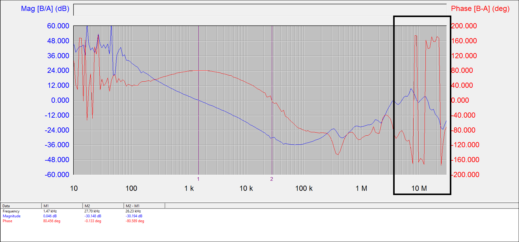
I tested a boost board loop response using LM5122 conference with TIDA-PMP20093 and the bode as shown below. I found the issue that the phase become very large and the mag start increase when the frequency is 5MHz. I wonder what's  the reason of this issue and how to solve it.

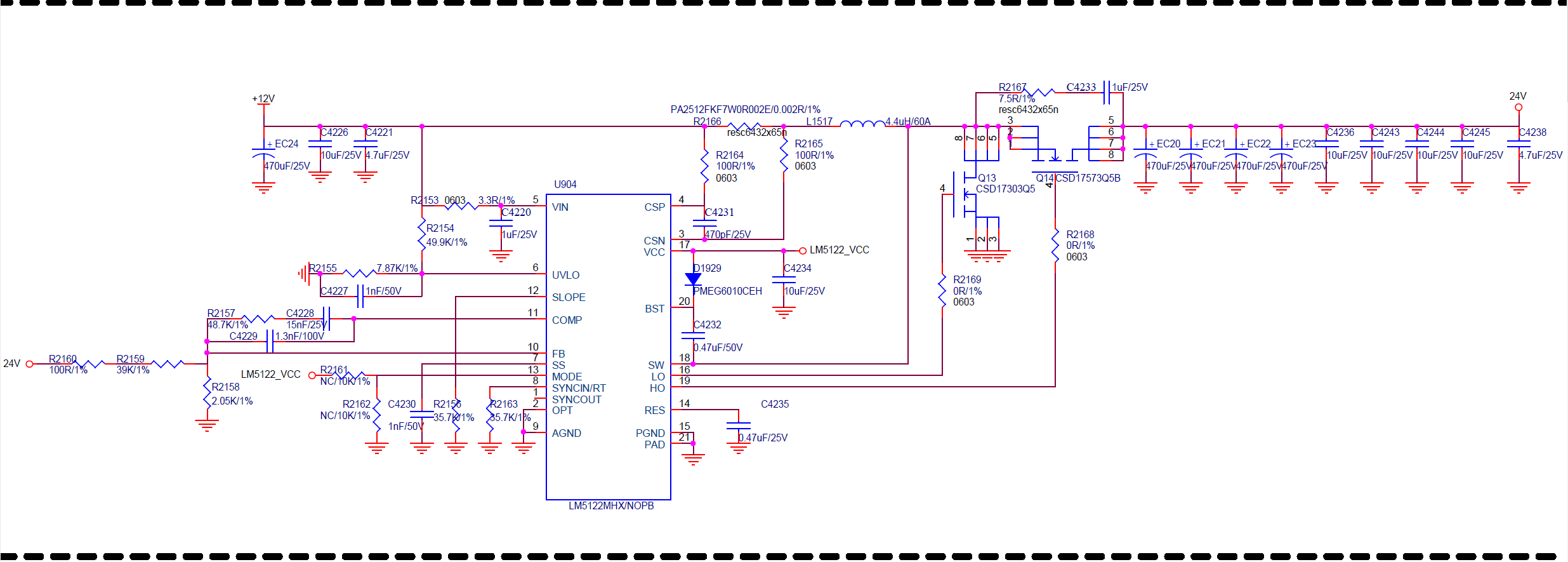
The spec of the boost board are: Vin=14.4V  Vout=24V. Because the limit of input range of Loop Analyzer(15Vmax), I changed the Vin=8.5V &Vout=14.2V & Iout=2A. The schematic as below shown.

  • Hi Betty,

    Phase and gain at 5MHz does not matter for this design. That is because the switching frequency is only 250kHz and the converter cannot reach to disturbances at 5MHz. To get ride on noise in the measurement please make sure that all wires used to connect to the board are short and connected with a twisted pair. 

    Thanks,

    Garrett

  • Hi Garrett,

    Thanks for your reply. But I also find that the bandwidth of this circuit is about 1kHz while the switch frequency is 250kHz. I refer to switch DC/DC knowledge and know that the band width always is the( 1/10~1/5) *switch frequency. so I wonder how to improve the dynamic response? Thanks!
  • Hi Betty,

    That bandwidth approximation is accurate for a buck converter, however in a boost converter there is a right hand plane zero in the control loop that must be considered. Because of this the crossover frequency of the loop is usually 1/3 to 1/5 the right hand plane zero frequency. That is why the crossover frequency is about 1kHz.

    Thanks,

    Garrett

  • Hi Garrett,

    Thanks for your answer. if you have any suggestions to raise the bandwidth for this design?Thanks!

    Betty
  • Betty,

    Please follow the datasheet section 8.2.2.19. This provides the equations to calculate the compensation components that will help increase the cross over frequency.

    Thanks,

    Garrett
  • Hi Garrett,

    I refer to the datasheet section 8.2.2.19 and calculate the compensation components, and the same time I simulated the lm5122 loop transfer function follow table 2 in page 28/29 using MATLAB. however the simulated result is about 2.7kHz, which has a big gap with calculated result(5.3kHz). And I have a confusion about transfer function, in page 42 and 43, the datasheet select cross frequency is 5.3khz, while the test result is about 2.7kHz.