This thread has been locked.

If you have a related question, please click the "Ask a related question" button in the top right corner. The newly created question will be automatically linked to this question.

EM1402EVM: Cells not Balancing

Part Number: EM1402EVM
Other Parts Discussed in Thread: BQ76PL455EVM, LAUNCHXL-TMS57004, BQ34Z100EVM, BQ76PL455A-Q1, BQ34Z100, BQ76PL455A

I have wired the EM1402EVM to the TMS570 as described in the TMS570 Active Cell-Balancing Battery-Management Design Guide. I am using NCR18650B batteries. I have wired 16 cells to the appropriate connector, and 4 cells to the 12V connection as recommended in previous E2E forums.

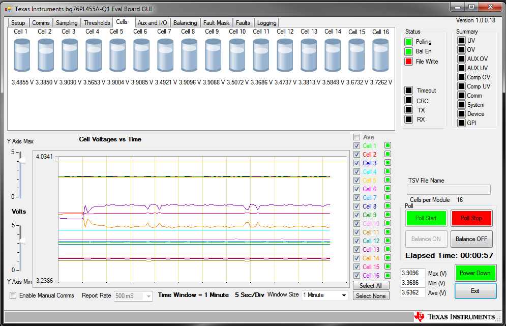
I am getting response back on the GUI, but the board will not balance the cells. When I begin balancing, cells 14 and 16 will invert relative to each other, for example if cell 16 is at 3.8V and 14 at 3.6V, it will show them switch and overshoot, showing that cell 14 is at 3.85V and 16 at 3.55V.

In addition, the voltage readout of cells 14, 15 and 16 are incorrect. The readouts for all other cells are accurate.

This problem has spanned two different EM1402EVM modules and two different TMS570 boards, in all configurations. This occurs without making any changes to the software on Code Composer, including a fresh install and driver downloads on a different computer.

Please let me know how I may be able to address this issue.

Thank you.

  • Hi Emory,

    Can you double check your connector wirings? It sounds like something may be incorrect.

    Try using the EM1402 example code found on the EVM page - it is a more streamlined version of the code because it is not emulating a second UART port on the TMS570. If you can use a logic analyzer to read the SPI commands, that will be useful. I would also be interested to see if there are any faults reported by the EMB1428 devices
  • When using this code, how are the connections made? in sys_main.c, it says to use connectors J3:1-6 and J7:1-3 on the BQ76PL455EVM, but these do not match with the connections on the EM1402EVM.
  • Emory,

    Are you using a pl455 EVM as a bridge? Or connecting directly to the UART of the EM1402?


    If directly to the EM1402 EVM, the UART header connections are the same, since they still go to the pl455. The header may be named differently, but it is still the white UART header.
  • I am connecting from my computer to the LaunchXL-TMS57004, and from there to the EM1402EVM. Attached is the comment I am concerned with.

    I assumed the 1402EVM J7 connector is the equivalent of the bq76PL455EVM J3, and connected these pins according to this instruction.

    The second set of pins labeled in this instruction I was unsure about. For those labeled as bq34z100EVM J7, I hooked up to the 1402EVM pin J2.

    With these connections, I was unable to connect to the board using the bq76PL455 GUI.

    Thank you.

  • Here are a few screenshots of the bq76PL455A-Q1 GUI when I use the TMS570BMS code.

    The EM1402EVM is attached to a TI LaunchXL TMS57004 via the following pins, provided in the "Active Cell Balancing using bq76PL455A-Q1" pdf provided by TI.

    Any idea why this might be happening? Or any help with the previous question about the EM1402EVM code?

  • Emory,

    It appears that there is an error in the comments - there is no bq34z100 on this evm (it is a guage device).

    J6 is the fine pitch header on the EM1402 EVM, right next to U3 (UART header). The J6 header gives access to the pl455 GPIO's, which also acts as the SPI lines, etc.

    J1 and J2 are the TMS570LS04 launchpad headers.

    Please also make sure you follow the TMS570 modifications in the design guide, i believe in Fig 6 and Fig 7. On the launchpad you must remove R8 and R9, as well as solder the TMS570emulated UART pins to U2, which allows you to use the pl455 GUI for ACB.

    J2 is the pl455 AUX pin header
  • The EM1402EVM sys_main.c code that I sent a picture of says that I must connect to the bq34z100 header j3, which as you said, does not exist. It also says that I must connect to the J7 header pins 1-3 on the bq76pl455EVM.

    On the EM1402EVM board, J3 is the connector to the battery cells, so I assume that is incorrect. The options that seem to make sense in this case is J7, a 6-pin Molex Serial connector - I found that this was designated as J3 in the manual, but not on the board.

    So, in the EM1402EVM code, it tells me to connect to J3 and J7 - which either appear to be the same header or at least one of the two is designated incorrectly.

    In the "Active cell balancing using bq76PL455A" pdf, it tells me to connect to the EM1402EVM headers J3 and J6. J3 seems to match up with the header described in the manual as J3 and labeled J7. In another help forum, ()  it was stated that these go to the header labeled on the board as J2.

    The header on the board that is labeled as J6 is the one that supposedly goes to the thermistor inputs.

    This inconsistent labeling is causing me a lot of problems. I am still not entirely sure that I am connecting everything correctly.

    However: When I have everything connected to the headers on the board labeled as J7 and J2, and using the TMS570BMS code, I am able to get the readings I explained before. Signals are going through and are recognized, but the board is just not balancing. The LED D4 lights up every four seconds for one second, which shows that it is attempting to balance (1 second balance, 3 second rest). Is there any specific part of the board or wiring that would cause this, so I can at least focus my efforts on one thing?

    I will attach a picture of the corner of the board in question as soon as I can.

  • Here is a picture of the corner in question.

  • Emory,

    As you mentioned, J6 is indeed for the thermistors.

    J7 is for the UART/bq76pl455 nFault/ bq76pl455 wakeup. if you wanted, this is the bare minimum for connections to be made. From here, you can bit-bang SPI commands to control the EMB devices.

    J2 brings out the pl455 GPIO pins, which are also the SPI lines, etc. You can connect these directly to the MCU if the MCU is controlling the EMB devices.

    It seems like you have things mostly working in your last paragraph. The LED blinking is a good sign - have you put a logic analyzer on the SPI lines to confirm that the correct commands have been sent?

    If the commands look okay - my next area to focus on would be the converter. Are the FETs being driven properly, is there any error from the EMB1428's being read, etc.
  • At the moment, I do not have a logic analyzer, but I can work on getting one.

    In the meantime, I replaced one of the cells from my 12V source because I found it to be dead. Now, I am able to reproduce the balancing waveforms I achieved earlier - but they still are not correct.

    Here is a picture of what I am seeing. Can you make any sense of it? It is apparent that there is an attempt to balance being made, but an overall change in voltage is not seen - the cells go back to their original voltage after each "balancing" period.

    Additionally, I do not think this should be a hardware issue, as I have tried it with 2 EM1402 boards and 3 LaunchPads, with the same results each time. 

    Let me know what you can make of this. Thank you.

  • I am still hoping to get an answer for this, any help you can give is appreciated.
  • Hi Emory,

    From that plot alone, I will not be able to diagnose what is happening. If the converter is not working properly, you will have to look for abnormal waveforms there.

    The spikes you see in your plot is the I*R drop from the balancing current. From that, we can see what "shape" the balancing current waveform is. If a channel looks abnormal (such as the orange/purple, we can look at those channels and start working from the cells to the converter to see what is happening.

    A question I should have asked a while ago- what cells are you using, and how many in parallel? I noticed that the GUI window has a 1 minute logging period - so you are only balancing for a few seconds. Even at 5A of balancing current, there will not be much capacity gained in the cell during that time period. This is probably why the voltage is not increasing.
  • I am using 16 NCR18650B Li-Ion batteries. For testing purposes, should I start with less batteries?

    Additionally, is there a way to change the balancing time? I was just using the standard time set in the demo. I had tried to change it previously but it didn't work correctly (but, at that time, nothing worked correctly)
  • Hi Emory,

    Are these in parallel (so 16s16p)?

    You could if you wanted. This configuration is fine - just know that the more capacity you have, the longer it takes to balance.

    For example, say you had 10 1000mAh cells all in parallel. For easy math, we can say it is a single 10000mAh cell. If you are balancing with 5A, it will take you 10Ah/5A = 2 hours to go from completely empty, to fully charged. A simple C-Rate calculation is usually a reasonable estimation of how long it will take to balance. In practice, this means that you really have one variable you can change - the balancing current. On the EM1402 this is done by changing the VSET DAC output.
  • Thank you.

    I found and resolved the problem occurring with cells 14-16: they each had loose connections and was throwing everything off.

    After fixing this, I am now getting no change when I try to balance. I let the program run for about an hour total (I got an error every 13 minutes 57 seconds, I will be looking into this later). However the indicator LED does turn on for 1 second every four seconds as it did before. Additionally, there is no difference between when I have the J2 (SPI/GPIO) connector plugged in vs. unplugged. This leads me to believe that my SPI communication may not be working correctly. I believe the charging/discharging command is sent through SPI. Where should I begin to look for problems with my SPI communication?
  • Hi Emory,

    Glad you found it!

    If the LED indicator turns on, that means the supply for it is being turned on.

    My recommendation is to watch the SPI bus and see if the data is actually being sent. You can also try to manipulate the VSET DAC output voltage, since that is SPI driven.

    If you see the correct SPI traffic, i suggest taking a meter and following the datapath and looking for something that may be damaged.