This thread has been locked.

If you have a related question, please click the "Ask a related question" button in the top right corner. The newly created question will be automatically linked to this question.

TPS92691: PWM dimming - overcurrent on resume of PWM

Part Number: TPS92691

I'm working on a project using the TPS92691.   It is fairly high power with vin 10 - 30 V dc, and a Vf string of LEDs of around 60vDC, driven at 1A.

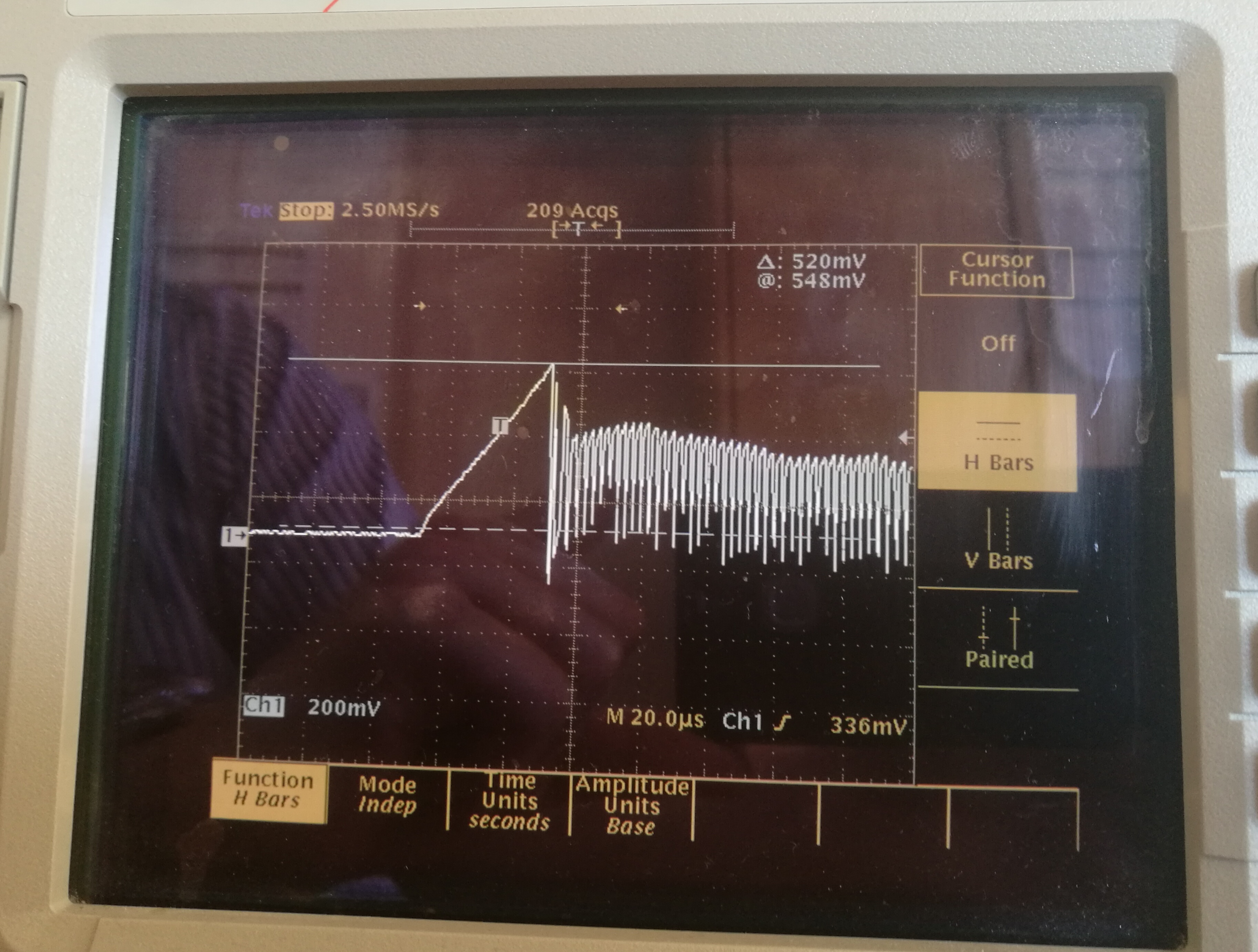
I am having issues with driving with PWM at lower input voltages - esentially I am hitting the current limit causing flicker, on the rising edge of the PWM signal.  The image shows the voltage across the Fet current sense resistor (0.03Ohms).  The problem is the initial peak ramp up of the current through the inductor seems to be higher than it should, before the switcher starts cycling again?

The data sheet states:

"On the rising edge of the PWM input voltage (VPWM > 2.5 V), the GATE and DDRV outputs are enabled to ramp the inductor current to the previous steady-state value. The
COMP pin is connected and the error amplifier and oscillator are enabled only when the switch current sense voltage VIS exceeds the COMP voltage, VCOMP, thus immediately forcing the converter into steady-state
operation with minimum LED current overshoot."

However this does not seem to be happening, and does not seem correct as the COMP pin voltage is ~2V, so Vis will never get that high?. 

Any suggestions other than increasing the current limit (it is now currently ~17A, which is already more than the saturaton current of the indcutor ~12A).

  • Hello,

    I don't think it is a current limit issue unless there is some noise from the layout or something else making it worse.

    That peak is usually present to some degree for various reasons but it can be helped in different ways. A few scenarios (can be a combo):

    1. If the dimming FET is turned off too quickly when PWM is pulled low the output capacitor can actually charge above where it should be a little bit. Then when it is turned back on it can dump more current that you would like from the output caps, through the sense resistor, and into the LED load. You can help this by adding a small delay in the FET turn off time to discharge the output caps a little more before it is off.

    2. I can also be the control loop as the bandwidth and gain change with different input voltages (or a combo of this and #1). If you can increase the bandwidth while maintaining stable operation it will generally reduce the overshoot pretty well also.

    3. In some cases it may help to put a high value resistor from COMP to ground (1M to 10M maybe). That will just discharge COMP a slight bit each cycle which can reduce the overshoot as well.

    It's unlikely you will get rid of all overshoot in a circuit where you are connecting and disconnecting large cap, but you should be able to get it so that the LEDs do not flicker.

    Regards,

    Clint

  • Hi Clint,

    Thanks for that - however it is not the LED current I have a problem with, this seems fine.

    The issue is with the initial ramp up through the inductor after the PWM is resumed. With lower input voltages this can ramp up and hit the inductor current limit (~525mV at the Is pin), shutting down the switcher for ~32uS then doing a soft restart. (the scope pic above shows when it is working OK without hitting the limit it was just to illustrate the differece between the inductor current on initial ramp up and during operation when switching).

    It is the initial ramp up that seems to be pulling a large current (more than I would have thought) through the inductor before switching resumes. The resistor from COMP to ground makes sense to dischard comp slightly during the off period - this should I guess reduce the ramp up peak current.

    I think I will decrease the current sense resistor value slightly, to increase the current limit to help.

    Thanks.
  • I see, I just could not see a current limit event in the picture but that makes sense now. That is a pretty high power application so the peak currents during PWM dimming can get quite high. Lowering the current limit may be the only real option. A higher inductor value might bring down the peak current a bit as well if that is something you want to try.

    Regards,

    Clint