


Tool/software: WEBENCH® Design Tools
Good morning, in the past I designed a Sepic DC/DC converter in order to manage a VIn in the range 8V-32V and a fixed Vout of 12V. Using Workbench I generated the proper schematic based on LM3488-Q1 device. After the board has been assembled I discovered that this logic was not working fine in the range 8V-13V; that means the logic works as StepDown , but not as StepUp.
I tried to reverify the schematic and discovered that now the circuit is different.
Can you help me in the understanding of the issue?
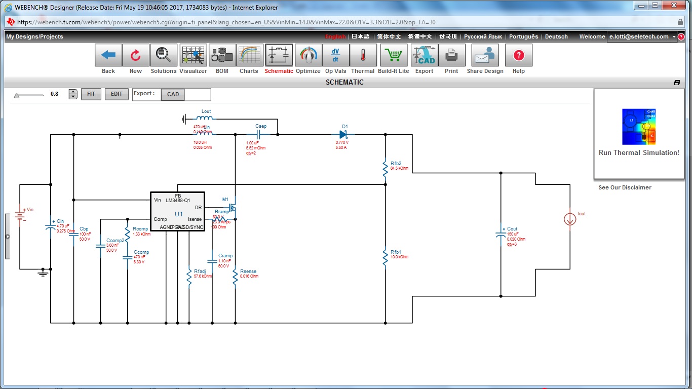
I can send you the first schematic I generated and implemented and the newone I regenerated today but also 1-2 weeks ago. I would like to know if there is a way to modify the initial schematic to have the StepUp working too. Eventually would like to know which is the correct schematic. 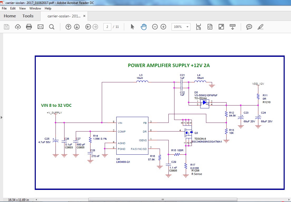 This is the new schematic from WorkBench.
 Thanks a lot for your support.
