


Hello,
I have built and run an LED driver as shown in the picture below. It consists of a few blocks:
- over-voltage protection and noise filtering,
- anti-surge protection,
- 16V regulator (that works as a voltage limiter for the LM3488 chip),
- 5V regulator for PIC chip,
- PIC chip that controls LED brightness using PWM.
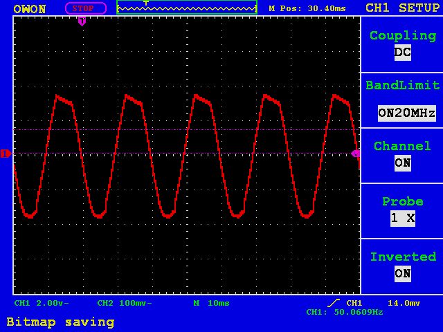
When the driver (and the LED load) is supplied from an autotransformer it works fine - no problems whatsoever (figures 2, 3). But when the supply voltage is taken from a traffic light controller (that uses triacs for switching the driver on and off) it quite often shows abnormal behaviour (figures 4, 5).
The heart of the driver is a SEPIC converter. I found, when I ramp the voltage up from 0V, the current is very high before the converter "kicks in". Then after everything is back to normal. Figure 5 indicates that the input voltage (coming from that traffic light controller) has its peaks cut off. I suppose this happens because each cycle (or half-cycle) the SEPIC converter requires high current to start and the source (traffic light controller) limits the current to prevent overloading.
Is there any chance to prevent the keying MOSFET Q4 from being on before the converter starts?
Figure 1 Driver diagram
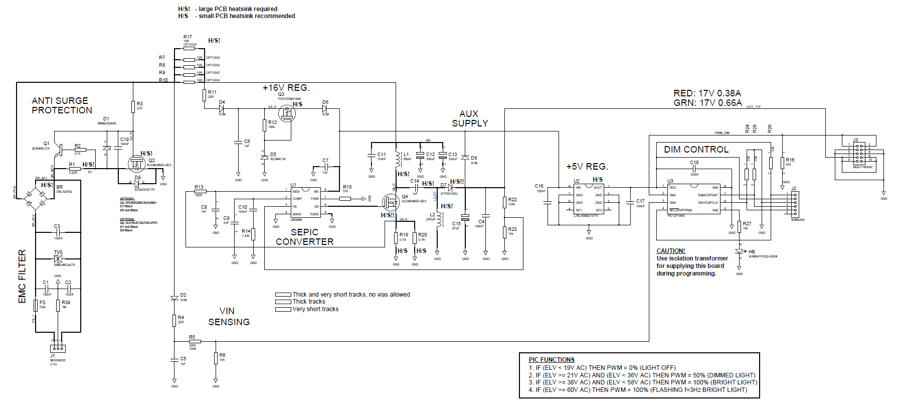
Figure 2 Normal function - input current

Figure 3 Normal function - input voltage
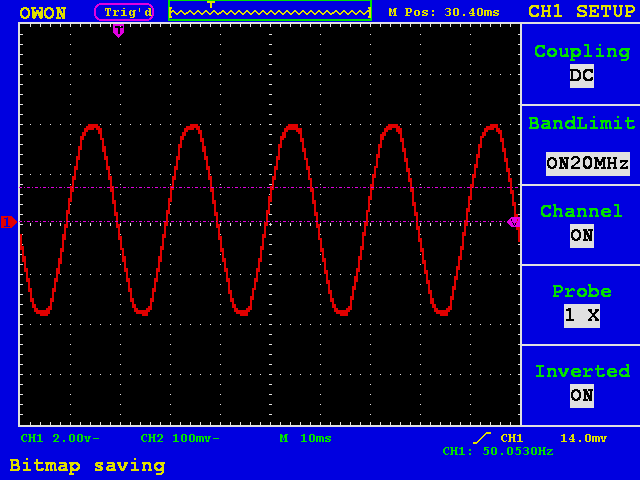
Figure 4 Abnormal function - input current

Figure 5 Abnormal function - input voltage
Thanks.
Kind Regards,
Piotr Rozycki

