Hello
I have problem with LM25011. I have 5 boards with this converter and all boards have the same issue. 2,4V on output (when input voltage is 8V). No PG signal. RT pin works as described in datasheet. D2 is B260A-13-F. VFB 1,1V.
One board have 3,1V output and 0,025V VFB
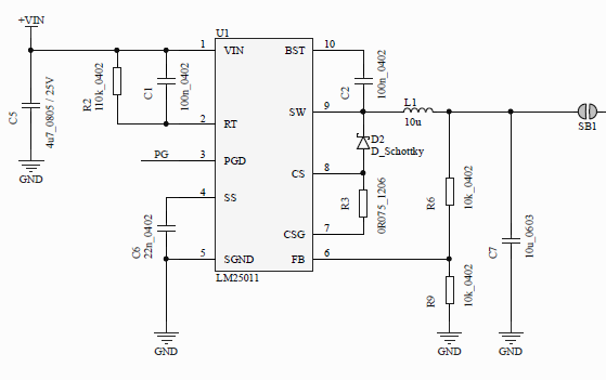
My schematic:
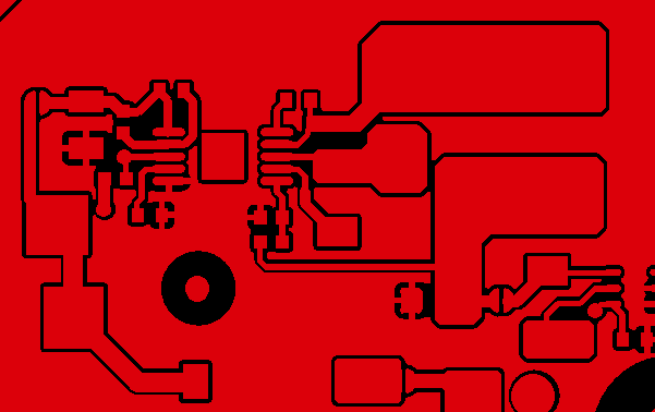
Layout:
Wave on SS capacitor:
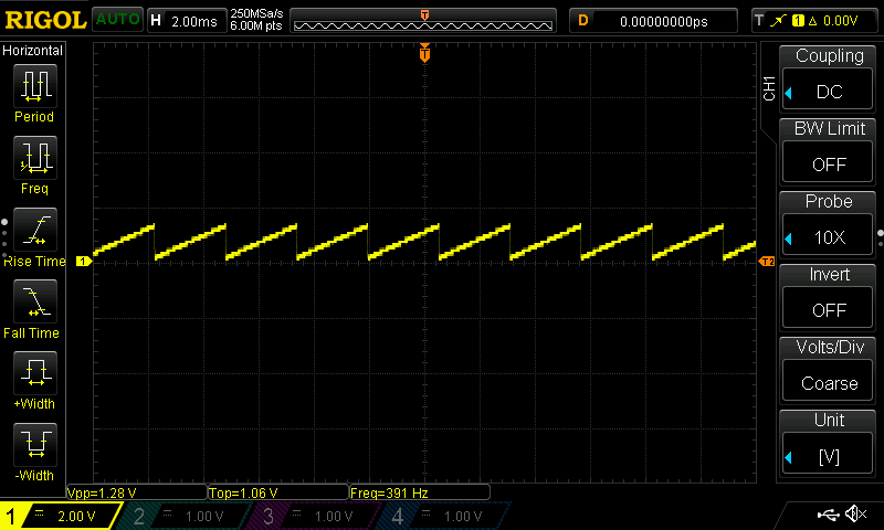
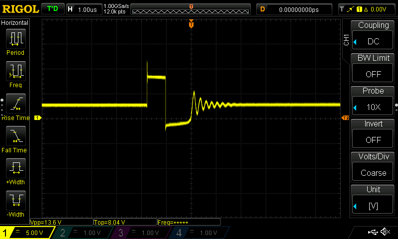
Wave on SW pin:
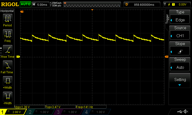
Waveform on BST capacitor: