Other Parts Discussed in Thread: OPA4188, , LM4040
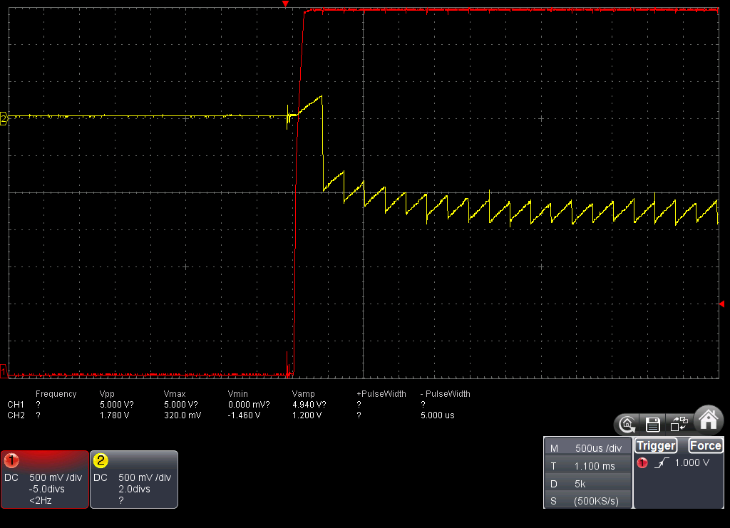
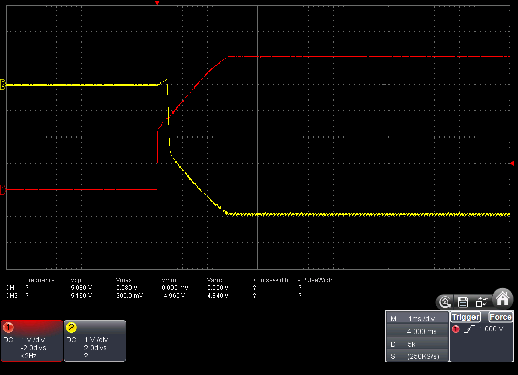
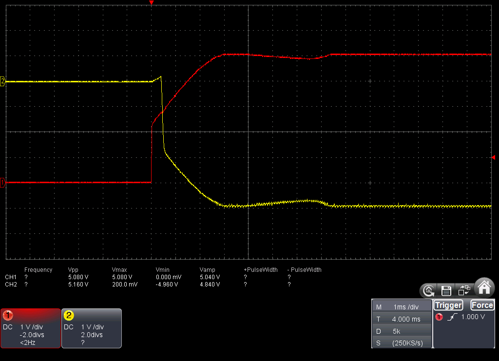
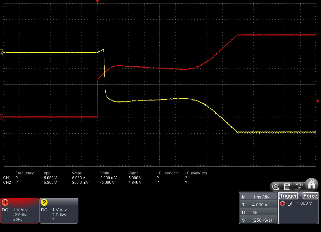
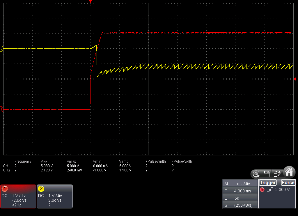
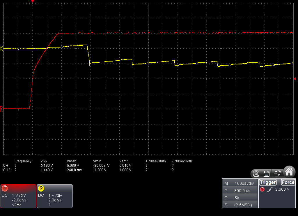
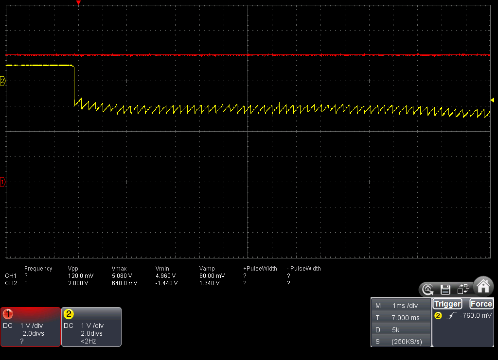
In a prototype PCB I have a linear power supply (120V to 12V then a LDL1117-5V regulator) that power the LM2776. The load are multiple OPA4188 amplifiers with a +5 and -5 supply. At startup, when using AC mains, *sometimes* the output of the LM2776 does not reach -5V but stay oscillating around -1.3V. If I use a battery to power the linear regulator directly, the problem always happens.
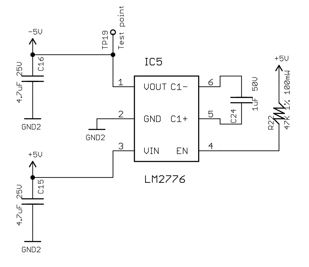
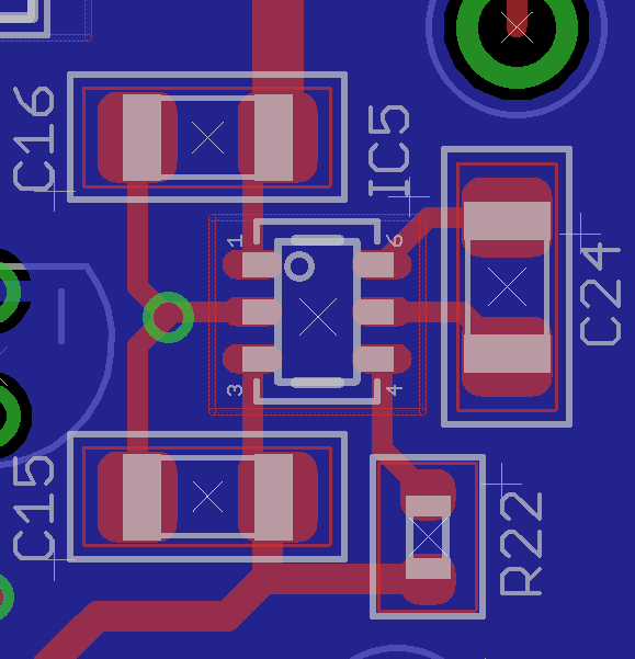
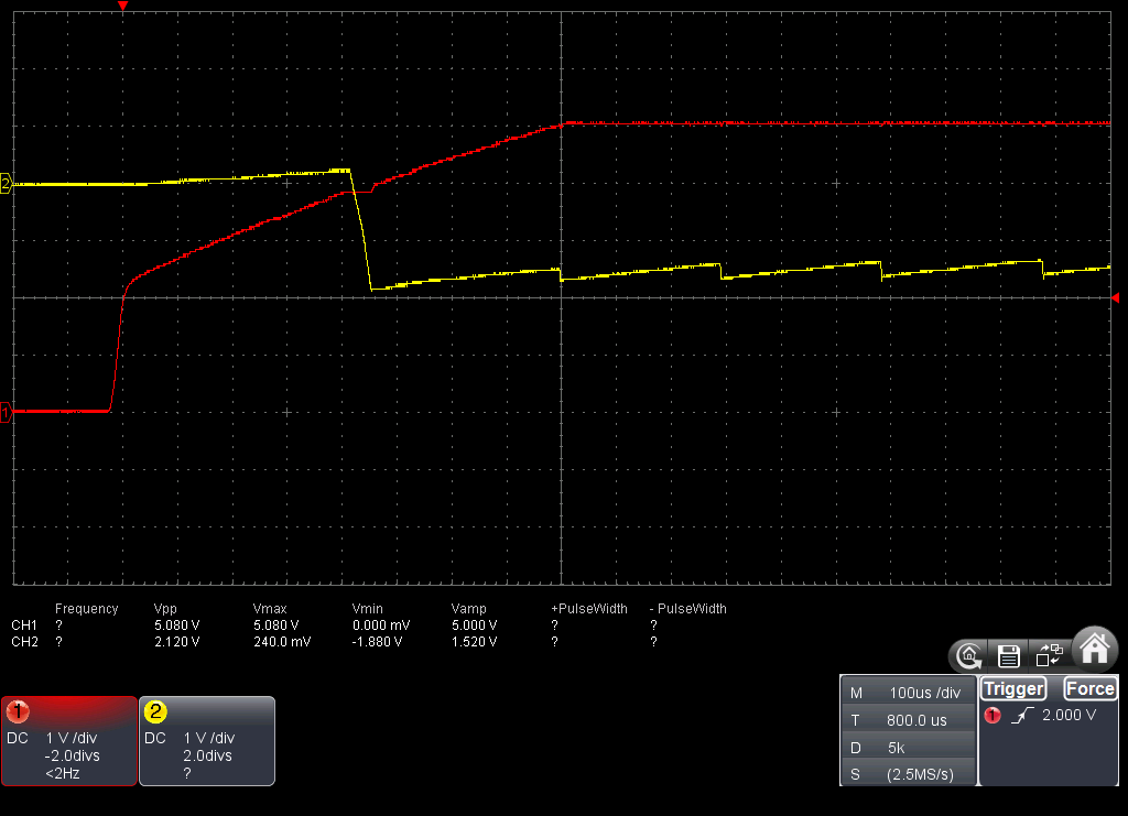
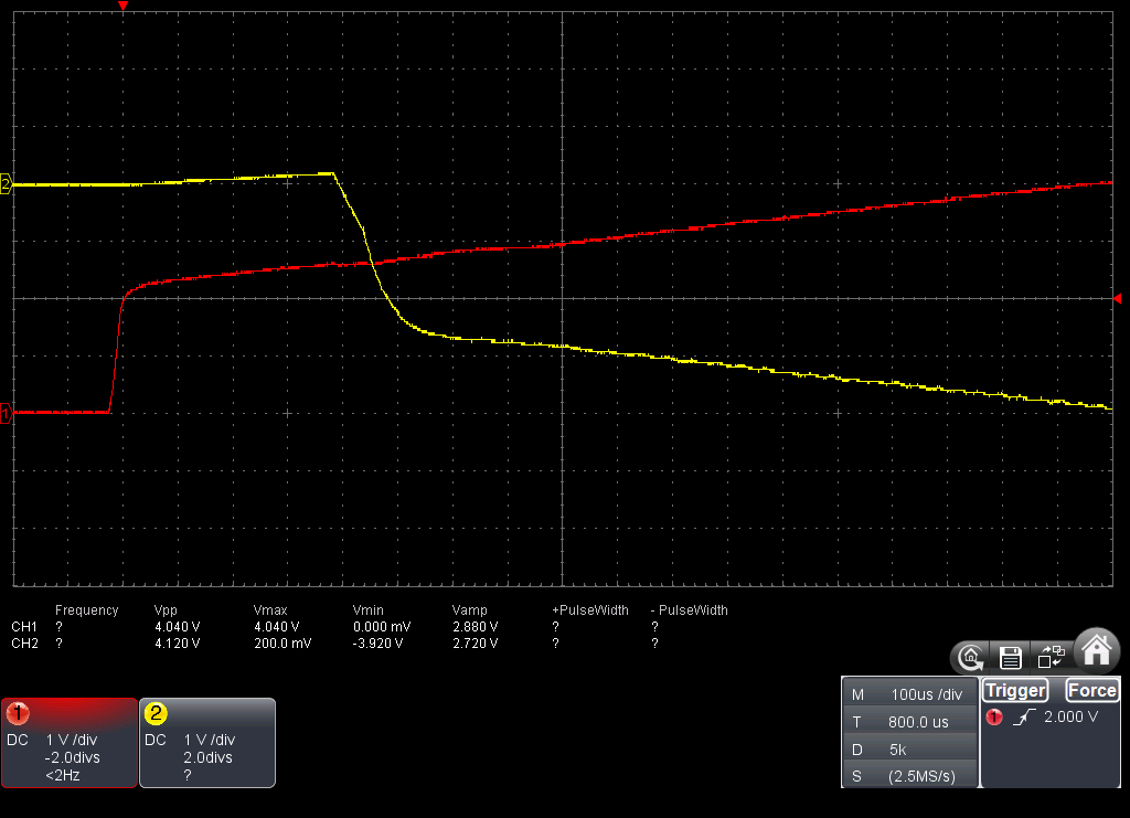
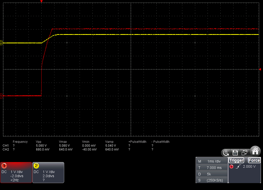
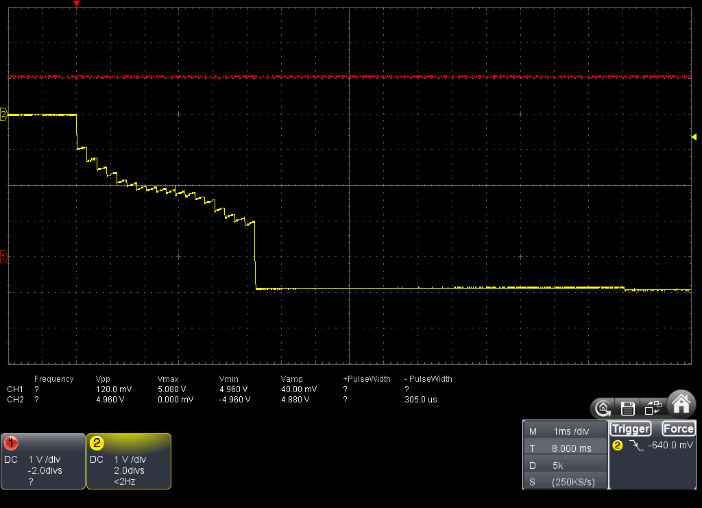
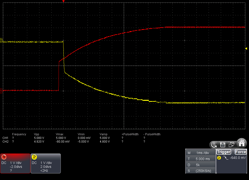
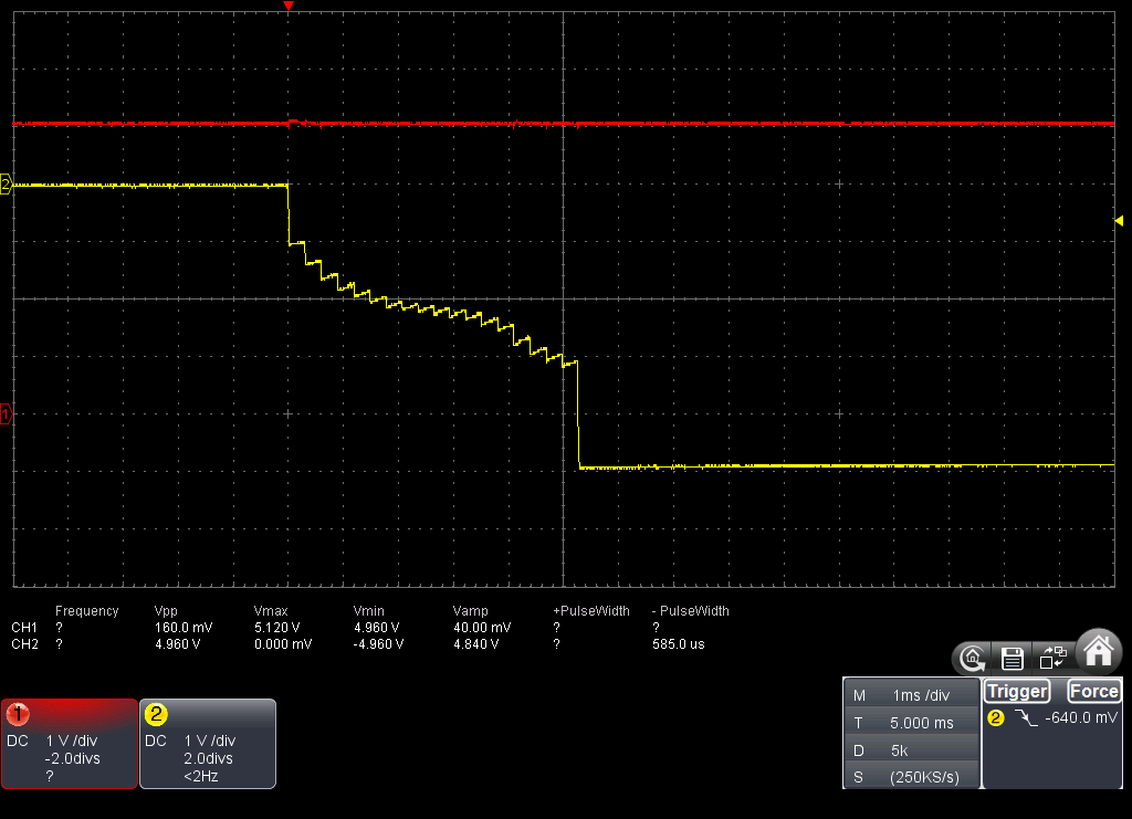
This is the schematic, PCB layout and Vin / Vout signals:
I don't know if this a layout issue or if the positive voltage in Vout before the LM2776 is enabled may cause this. The only difference I can see between a failed startup and a successful one is the slope of the linear regulator output voltage (depending at what time of the 60Hz AC cycle is turned on, its output voltage raise faster or slower).
In case it matters, the following are the component parts:
| Parts | Value | MF | MPN |
| C24 | 1uF 50V X7R 10% | Murata | GRM31MR71H105KA88K |
| C15, C16 | 4.7uF 25V X7R 10% | Murata | GRM31CR71E475KA88L |
| R22 | 47K 1% 100mW | Yageo | RC0603FR-0747KL |
| IC5 | LM2776 | Texas Instruments | LM2776DBV |
Any suggestion is welcome. Thanks in advance.


