This thread has been locked.

If you have a related question, please click the "Ask a related question" button in the top right corner. The newly created question will be automatically linked to this question.

TPS65131: Vneg voltage oscillation issue

Part Number: TPS65131

Hi

I have an issue from my customer. Could you support for this issue?

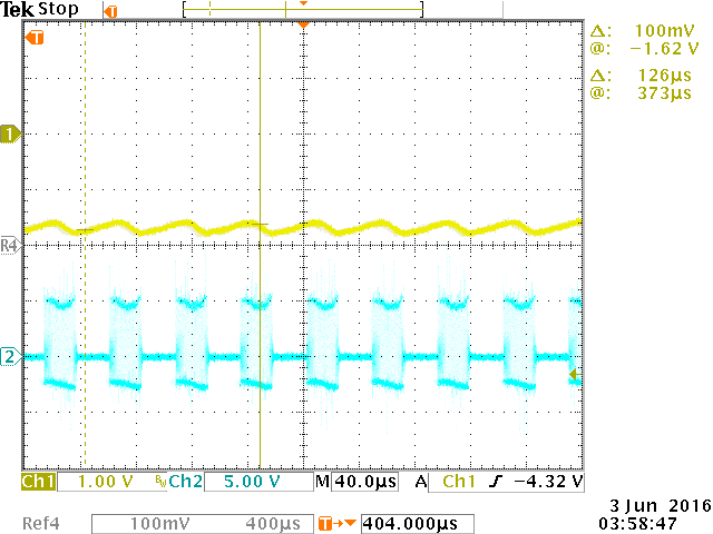
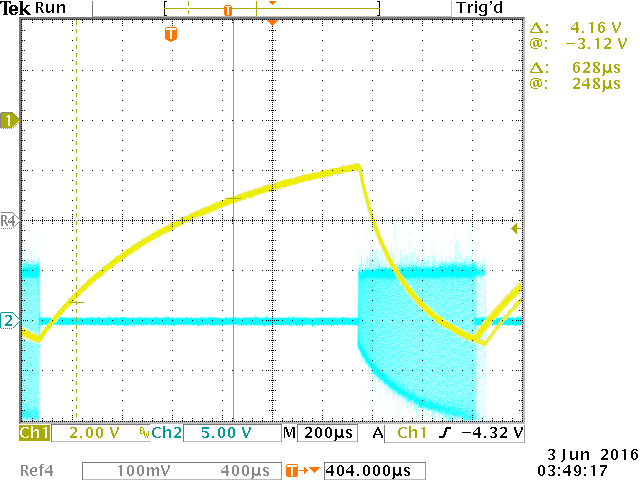
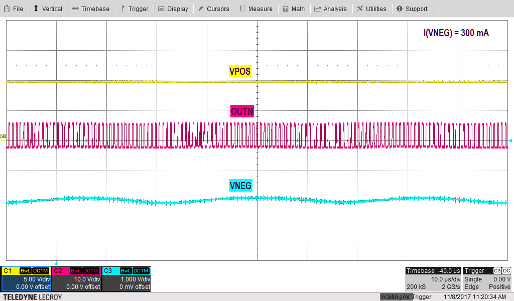
Vneg voltage has oscillation when negative output voltage set -2V and load is over 100mA.


Customer conditions

Board : Customer designed board

Vin=5V

Vout(neg) = -2V setting

L : 4.7uH

Cout : 10uF x2


I tried to check with our EVM.

I confirm same behavior with TPS65131EVM.

I seem, this behavior improved when I modified following external components. (not perfect improve)

  • Inductance decrease to 1.0uH

  • Output capacitance increase to 200uF.


Could you check about it? And, Could you give me your advice for improvement and cause of this issue?

Thanks

Yusuke Mukuno

  • Hello Yusuke Mukuno,

    Please increase the inductor again to the recommended value 4.7uF. The output capacitance should be 4* 10uF. Please check if the feedforward capacitor at the feedback divider is calculated correctly.

    Best regards,
    Brigitte
  • Hi Brigitte-san,

    First, I tried to evaluate by correct value in datasheet regarding inductor and output capacitor.

    Also, I tried to modify Cf as below,

    1. L=47uF, 10uFx4, R3=1Mohm, R4=600kohm, Cf= nothing, 2pF, 3pF, 5pF and 10p.  (Correct value by Equation 12 is 7.5pF. )

    2. L=47uF, 10uFx4, R3=100kohm, R4=60kohm, Cf= nothing, 10F and 33pF. (Correct value by Equation 12 is 75pF. )

    However, the oscillation become bigger when feedforward capacitance increase. And output voltage DC level was increasing....

    So, I tried to modify the inductor and output capacitors.

    And, This behavior improved when I modified following external components. (not perfect improve)

    • Inductance decrease to 1.0uH
    • Output capacitance increase to 200uF

    I understand, this value is not-recommended value by datasheet. 

    Could you please confirm this behavior with EVM in your side? I think, you can find this strange behavior.

    Datasheet

    Regarding Cf

    C10 = 7.5us / R3  : Equation 12 

    Regarding divider

    Feedback divider current considerations are similar to the considerations at the boost converter. For the same reasons,

    the feedback divider current should be in the range of 5 μA or greater. The voltage across R4 is 1.213 V. Based on those values, the recommended

    value for R4 should be lower than 200 kΩ to set the divider current at the required value.

    Thanks

    Yusuke Mukuno

  • Also, I have a question.
    What is the control topology in this device? peak current control? voltage control? or hysteresis control?
    I cannot find about control topology in the datasheet.
  • This is typo.

    L=47uH  >>>  4.7uH

  • Hello Yusuke Mukuno,

    Please excuse me, but I could not reproduce your application up to now. At the moment the team is reduced to just me and I am not in the office at the moment, so I need to postpone measurements to next week.

    Best regards,
    Brigitte
  • Brigitte-san,

    I attached the wavefrom as below,

    1. L=4.7uH, Cout=10uF x4, R3=100kohm, R4=60kohm, Cf=nothing

       Yellow: Vout, Blue : SW node

    2. L=4.7uH, Cout=10uF x4, R3=100kohm, R4=60kohm, Cf=10pF

       Yellow: Vout, Blue : SW node

    Could you please check those waveforms? Also, please give me your advice for improvement.

    Thanks

    Yusuke Mukuno

  • Yusuke-san,

    Thanks for the measurements. Could you provide us the schematic as well as the layout of your application?
    Please be aware that the regulation loop of this part is susceptible to noise. It must to be made sure the feedback/feedforward network as well as the compensation network needs to be routed noisefree on the signal site as well as on the ground site.
    If you place a 50-kOhm damp resistor in series to the feedforward capacitor , will this improve the behavior?

    Best Regards.
    Ilona
  • Ilona-san,

    Thank you for your reply.

    I measured those waveform with our EVM. Please refer the user guide for schematics and layout.

    I will try to check with 50kohm resistor.

    Yusuke Mukuno.

  • Ilona-san,
    I try to add damp resistor 50kohm. The oscillation pk to pk is decreasing a little. However, it don't improve.
    Could you please check it in your side with EVM?
    And, could you please let me know about your recommended external components for -2V setting?
    I can find this issue with following conditions
    Vin=5V
    Vout(pos) = -2V setting
    Iout= 300mA
    L=4.7uF, Cout=10uFx4, R3=100kohm, R4=60kohm


    Also, customer hae additional question
    customer found the oscillation voltage issue on positive rail too.
    Oscillation pk to pk : 100mV~200mV
    Vin=5V
    Vout(pos) = 10V setting
    L : 4.7uH and 22uH (Both condition)
    Cout : 10uF x4
    R1=1Mohm, R2=138kohm
    Could you please check it?

    Also, Could you please let me know about this device controll topology?

    Yusuke Mukuno
  • Hello Yusuke-san,

    Thanks for confirming this. Yes I will have a look at this in the lab tomorrow and get back to you afterwards.

    Best Regards.
    Ilona
  • Hello Yusuke-san,

    I've tried to replicate your observation but so far was unsuccessful, see scope plot (PSN=OFF). Output voltage ripple of VNEG is not acceptable, no affection of VPOS. Similar behavior I see with PSN=ON accept that it skips pulses at a lower frequency ~200 Hz.


    This is measured with settings as you proposed (VI=5V, Load = 300 mA and PSN=OFF). Tomorrow I will check further more on the feedforward network.

    Can you describe the modification you did exactly when the ripple started to increase? Did you use other caps and inductors (but kept the values the same)?

    Thank you.

    Best Regards.

    Ilona

  • Ilona-san,

    Thank you for your checking.

    Sorry, my EVM is broken. So, I cannot recheck it soon. I ordered one more EVM.

    I found VNEG issue with following conditions.

    Vin=5V

    Vout(neg) = -2V setting >> R3=100kohm, R4=60kohm

    Iout= 300mA

    L=4.7uF, Cout=10uFx4,

    Cf= nothing and 10pF

    PSN = ON

    Regarding VPOS oscillation.

    >> I seem, it is light load mode. I discussed with my customer. (it is ok)

    Is  the oscillation of your waveform at pulse skip mode? (PSN = ON/OFF)

    If yes, Could you explain about the conditions of becoming pulse skip mode?

    At PSN=OFF, I seem, this wavefome frequency is about 33kHz (30us).  How do you think about cause of this Vneg wavefome?

    At PSN=ON (lower frequency ~200 Hz), If you can post the waveform on E2E, can I see the waveform? Do it have too big ripple? 

    Thanks

    Yusuke Mukuno

  • Hello Yusuke Mukuno,

    I expect that the 60k resistor connected to VREF draws too much current out of VREF, causing the reference to get instable. If the reference is instable, both output voltages will reflect this.

    In the electrical characteristics the current that is tested to be available on VREF is 10uA. With 60k you draw more than 20uA out of the reference.

    Best regards,
    Brigitte
  • Brigitte-san,

    Thank you very much for your answer!

    Customer tried following conditions.

    1. L=4.7uF, 10uFx4, R3=1Mohm, R4=600kohm, Cf= nothing, 2pF, 3pF, 5pF and 10p.  (Correct value by Equation 12 is 7.5pF. )

    2. L=4.7uF, 10uFx4, R3=100kohm, R4=60kohm, Cf= nothing, 10F and 33pF. (Correct value by Equation 12 is 75pF. )

    I will try to check R4=240kohm, R3=400kohm. It is REF current = about 5uA. However It is over 200kohm(it is out of datasheet recommendation.).

    If I will have any update, I will post E2E again.

    Yusuke Mukuno