This thread has been locked.

If you have a related question, please click the "Ask a related question" button in the top right corner. The newly created question will be automatically linked to this question.

BQ2973: Charging and using 3x Li+ batteries in parallel

Part Number: BQ2973
Other Parts Discussed in Thread: BQ21040, , BQ28Z610

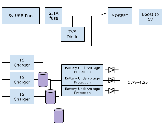
The idea is to make a battery setup in such a way that the user can use 1 or 2 or 3 18650 Lithium cells. The circuit would draw power via USB to charge the setup as well as run the application circuit after the boost section. The load is around 500mAh.

An p-Channel mosfet is used to act as a switch for the final output. USB-5v is connected to the gate of the mosfet, the output of the UV protection circuit is connected in parallel to the drain of the mosfet. So as soon as USB is shut off, the circuit would draw power from the battery pack that is connected. Circuit referencefrom ESE answer.

The main reason to use the setup was to allow the user to use 1S by default. If the lifetime of the application circuit was to be extended, the user attached another 1S to the setup. So the boost section ( 3.7v-4.2v to 5v) remains the same.

Questions

  • Is it safe to use 3 separate charging ICs and 3 separate 1S battery protection ICs to charge 3 separate Li+ batteries?
  • Is is safe to draw power by connecting the output of the protection circuits in parallel (after the diodes)?

Charging IC choice : bq21040

Protection IC choice : BQ2973

For safety reasons I'd like to consume the battery only till 3.4v. ( so the working range would be from 3.4v - 4.2v).

Now, if more than 1 batteries are connected as above, how would anyone stop 1 battery from going below 3.4v?

Eg Bat 1 : 4.1v, Bat 2: 3.8v

  • Would they both drain together? Or would bat2 drain first/faster and then Bat1 start draining?

We are planning to keep the charging current at 500mAh. So at any given point int time, we'd be drawing 2000mAh from a USB port.

  • If this is plugged to a laptop USB port and the port allows only 500mAh to be drawn, is there a chance of anything going bad?

  • Hi User,
    The bq297xx series of protectors can only be configured for UV up to 2.8V, so it can't prevent discharge below 3.4V, something in your system would need to tell it to stop using the battery. For the battery to stop you might consider a gauge with configurable parameters such as the bq28z610.
    If the batteries are at different voltages as you illustrate, the highest battery will discharge to provide the load and the other diodes will be reverse biased or not fully forward biased. Once the cells are at the same voltage they will share current.
    If the system is plugged into a low current USB port the available current will be limited. You should manage the load of your system to not overload the port, see the USB specification.
  • Thanks for your thoughts. 

    W.r.t the schematic design of the above block diagram, We will be stopping utilization after 3.4v on the parallel battery section. 

    Could you please let me know your thoughts about the below implementation.

    Notes:

    Diode : RB056L-40TE25

  • Attached schematics below. Needs review to solve the issue
  • Hi User,
    It would appear you have the bq2970s backward, see the simplified diagram on page 1 of the bq2973 data sheet. It seems you should swap the GND and BATTERYn- connections for IC1, IC3, IC5. Same for IC2, IC4, IC6, the charge FET should be closest to PACK- which seems to be GND in your system.
    Also with IC2, IC4, IC6 the same names are used for most pins. Many design tools will short signals together by name, be sure the connections are made as you intend. The bq2973 will not work with multiple drive pins connected together.
    For R33, R34 and similar gate-source resistors the bq2973 data sheet recommends 5M resistors rather than the 1M shown.
    Hope this is helpful. Be sure to check all circuit connecitons.
  • Attached updated schematic. Please advise

  • WM5295 could you please let me know your thoughts about the above update
  • Hi User,
    I don't recognize your cell connections in the revised schematic. It does not seem the cells are protected as drawn.
    The bq2973 BAT and VSS should connect across the cell through the 330 ohm filter resistor.
    The 2.2k resistors (R43, R36, R40) should connect to the pack- of the system which seems to be your GND.
    The chargers all reference GND, which is PACK- for all the protected cells, the thermistors (R11, R48, R49) should reference GND also so that they do not bypass the protection FETs.
  • Hey ,

    Thanks for your notes. Schematic is updated. Could you please verify.

  • Hi User,
    It seems the bq2973 is implemented for proper operation. It is your design, be sure to check carefully.
  • Thanks for the support .

    Really appreciate it