This thread has been locked.

If you have a related question, please click the "Ask a related question" button in the top right corner. The newly created question will be automatically linked to this question.

LM5017: LM5017 Isolated DC-DC convertor circuit designing

Part Number: LM5017

Hello,

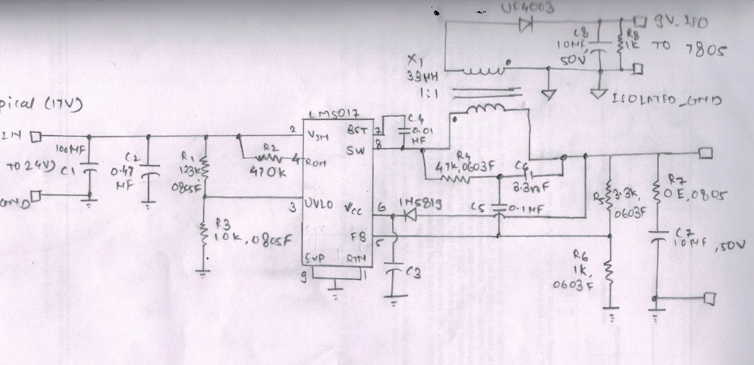
    I am designing isolated DC-DC convertor using LM5017. My specs are as follows:

1. Input Voltage range: 14V to 24 V DC (150 mA )

2. Output voltage range: Typical 5V /  9V isolated ( 100mA).

   For isolation purpose, i am using 1:1 isolation pulse transformer. My application is to power RS485 communication. Whenever i am attaching load to isolated output, my output is dropping to 4.43V .

   Kindly help me on this. If anybody has standard schematic desigined for such, please share with me.

  • Praful,

    A popular way to isolate a buck design is by using a flybuck topology.  See design steps here.  Can you share your schematic?

    -Sam

  •    Hey Sam, 

          Thanks for your reply. Here i have attached my designed circuit. Vin = 12 V to 24V (Typical 17V). Vin is given by 3 phase AC capacitive power supply. My Vout is typical 9V_isolated which is further given to 5V regulator. Typical application is  isolated 5V for RS485 communication.

      Whevener i am attaching actual load, my 5V is dropping to 4.3V whcih needs to stabilized. Please help me in this.


  • Praful,

    I'd like to check a couple things:

    1. You say loading the circuit brings the 5VOUT to 4.3V.  Is the input to the 5V regulator dropping from 9V to <5V or could this drop be an issue with the 5V regulator?  Have you selected the 7805 for a particular reason or could you go with an LDO with a lower dropout voltage?

    2. You mention Vin is given by 3 phase AC.  Is the input 12V-24V DC?

    3. R5 and R6 should give you an output of 5.26V.  If you want 9VOUT, R5 should be around 6.3k.

    The rest of the circuit looks really well designed.  Another culprit for losing regulation is the layout.  If the above notes do not solve the issue, please share the layout.

    -Sam

  • Thanks Sam,

      The main power supply of design is 3 phase AC capacitive supply from which DC voltage is generated. This supply is given as VIN to LM5017.

     As you mentioned i will re check value of R5 and R6.

     Is value of RON is sufficient or need to reverify?..

  • Praful,

    Get back to me about R5 and R6, plus the 7805.

    Are you referring to RON of the internal FETs in LM5017? If so, yes, the RON is more than capable of passing 100mA.

    -Sam
  • Hey Sam,
    1. You say loading the circuit brings the 5VOUT to 4.3V. Is the input to the 5V regulator dropping from 9V to <5V or could this drop be an issue with the 5V regulator? Have you selected the 7805 for a particular reason or could you go with an LDO with a lower dropout voltage?
    -- before attaching load my input voltage to 7805 is 8.9V constant. After attaching the load, input to 7805 is dropping to 4.3 to 4.9 V. Should the switching frequency of transformer to be changed??
  • Praful,

    You are completely right.  I was thinking of the wrong Ron.  Yes, with Ron=470k and VIN=17V, TON~3us (fig5) which at 33uH will give a peak current around 1.5A.  The part will enter current limit at 1A.  So yes, you should reduce Ron.

    RON should probably be around 250k or smaller.

    Thanks,

    -Sam