This thread has been locked.

If you have a related question, please click the "Ask a related question" button in the top right corner. The newly created question will be automatically linked to this question.

BQ76PL536A: Hardware design on CS_H of the base bq

Part Number: BQ76PL536A
Other Parts Discussed in Thread: , BQ76PL455A-Q1

Hi everyone,

i am using three bq76pl536s in a bms project ,  my question is about the CS_H  design of the bq on the bottom chain, i wonder if there problem on my SCH ;

i do as the follow :


http://www.ti.com/lit/ug/tidub04/tidub04.pdf  page 15.

but ,the question is,when i set the resister between CS_H and LDOD  is 1k; i found that the LDOD canot go up normally such that it keeps 0V ;

when  i set the resister to 5.1k; and it works normally;

so i wonder which value of the resister is suitable or the sch itsself is wrong;

the othe question is ,in some product of this project ,some bq consumes high current after it goes to sleep a period of time ;it seems like the bq active itself after it went to sleep fo a period of time; 

  • Did you clear the ALERT [sleep] bit?
    IF not then you will see current increase because of ALERT bit.

    1K pull up to LDOD is okay. 5.1K is still okay.
    We have 1K pull up to our evm and found no issues.

    ARe you loading extra to any of LDOs? There is max loading to the device.

    No issues reported with 1K.
    Do you think you can share the schematic with me?
  • Thanks for your reply Hwang;

    below is the status of all the bq  in sleep model: ( i have 15 Ultracapacitors ,each bq manage 5 ;and the sixth short to the fivth;so the sixth is UV all the time;

    i wonder how to keep out the fault caused by the sixth )

    Device_address 1 DEVICE_STATUS_REG :129

    Device_address 1 Alert_Status :0

    Device_address 1 FAULT_STATUS_REG :2

    Device_address 1 COV_FAULT_REG :0

    Device_address 1 CUV_FAULT_REG :32

    Device_address 2 DEVICE_STATUS_REG :129

    Device_address 2 Alert_Status :0

    Device_address 2 FAULT_STATUS_REG :2

    Device_address 2 COV_FAULT_REG :0

    Device_address 2 CUV_FAULT_REG :32

    Device_address 3 DEVICE_STATUS_REG :129

    Device_address 3 Alert_Status :0

    Device_address 3 FAULT_STATUS_REG :3

    Device_address 3 COV_FAULT_REG :24

    Device_address 3 CUV_FAULT_REG :48

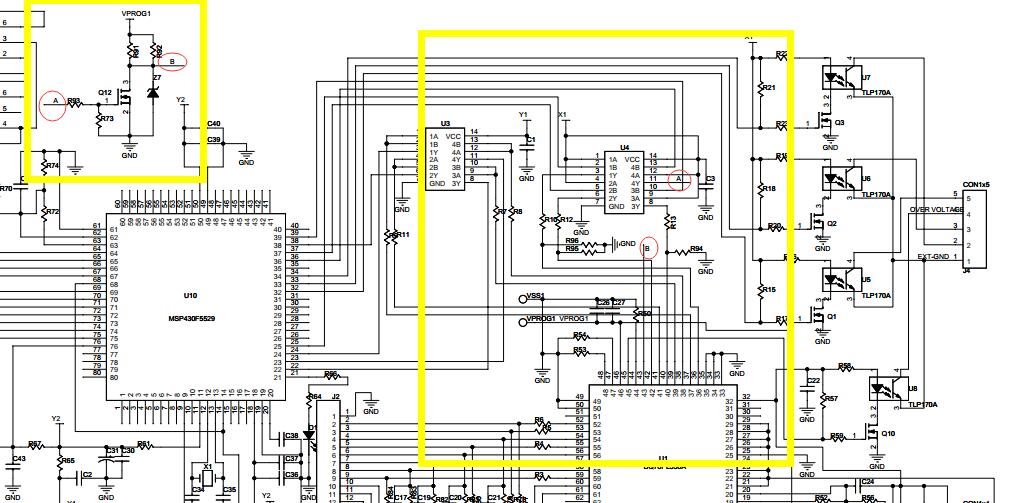
    and  my SCH is below:

    when the bq in sleep state ,The power of the mircro cpu cut off ,and just bqs remain its power from the battery ;

    besides, the voltage of REG50 goes down slowly ; and the CS_H of the bottom bq,goes up to almost 4.75V ~4.9V;

    the current flow into the vcc of the bq in the bottom chain is about 12~15uA ;

    So this work state of the bq looks like very good; but the fact is , this three bqs  consume much more current (guess :above 2mA )after several days () later differently;


    Now i donot know when and How the bq begin to work abnormally;  The moment i found the this issue,the voltage of the total bq went to almost zero cost by the bq itself ;

  • your schematic looks okay. I would use 10K pull-up to LDOD. 10K is still consider strong.

    It's not a problem but this is something you need todo everytime you connect cells to PL536A.

    You have to clear ALERT and FALUT registers.

    You will have ALERT and FAULT conditions when you 1st time connect your cells.

    You are seeing high current because you have FAULT register bits.

    1. You need to make sure you don't have UV or OV condition.

    2. You have to write 1 and 0 to clear the FAULT and ALERT.

    For example, you can write 0xFF and 0X00 to register 0x20 and 0x21 then you will clear ALERT/FAULT registers.

    Finally, your status " DEVICE_STATUS_REG :129"  I guess this is decimal not Hex.

    I don't understand how it can be 0X81 when you have FAULT condition.

    It should be 0xC8 which is 200 in dec.

    Just double check..


  • Thanks;

    As i said, One bq  support  6 series cell, but i just use the bottom 5;and short the vc6 to vc5; 

    in the soft  ,ADC_CONTROL REGISTER  is set to 0x04 to correspond the 5 cell;

    but the CUV_FAULT always 0x20 (the sixth cell is UV) , corresponding ,the FAULT_STATUS_REG is 0x02 (fault by uv) ;

    but the DEVICE_STATUS REGISTER  is 0x 81,it should be 0xC1; could it be said that  i had cleard the [FAULT] bit ?

    we know the sixth cell is short to the fivth ,so its voltage is 0;ofcourse it will cause UV fault ,but how can i disable the UV detect just of this cell ?

    i also had cleard the Fault[uv] bit , but no effect;

    Another question: 

    My SCH is short the vc6 directly to BAT on the pcb ,is this OKay ? 

    Is necessory to seperate it to power the bq in order? for example ,first connect the cell to vc0 to vc6 ,and then connect BAT to vc6 ;

    If not ,is any problem ?

    thanks very much;


  • GOto datasheet 7.6.3.22. You have to config number of cells for OV/UV. IF you have 5cells then you have to disable cell6. If not, then you will have FAULT all the time.

    You can connect cell in any sequence but it's best for 536A if you connect from GND, Vc1 and VC6 order.

  • Hi Roger Hwang,

    i canot find 7.6.3.22 in the datasheet of the bq76pl536A ,but in bq76pl455;

    During the test ,i found that the FAULT pin of the bottom bq is high when the bq actived ,but it becomes low when the bq inter sleep model;

    Is any other  possible reason will cause the bq active or enter some state that cost big current ?

  • GO check this link.

    You need to set FUNCTION_CONFIG Register (0x40) register to 5S to avoid OV/UV fault for V6 cell.

    Search on bq76pl536a-q1 datasheet. they are  same.

  • Hi ,Roger;

    i am sorry for this late reply;

    Your advice  resolved my issue , and i had keep out the Faults signal acorrding to set the register 0x40; Thank you very much;

    But i have another question :

    In this project , My cpu soft flow liks this below :

    Check the total voltage below a pre set point,-->set all bq IO_CONTROL[SLEEP]  bit;--> clear the alert bit-->cut down the power of the system except bq (the power of the bq from cell );

    In this sleep model : the CS_H is pull high by LDOD ; Pin of SDI_H,SCLK_H,CONV_H  pull down to gnd of the base bq .

    and i had test the current cost in vcc of each bq in this sleep model as below;

    the current to vcc of the base bq1 is 26uA;

    the current to vcc of the second and the third bq is 12uA; and the REG50 is 0V of each bq;

    As decribed above; i canot find any problem;

    but after about several days ,some system  work abnomally ,and i had do this below test;

    the cells on each bq Power Consumption differently ; the most serious bq wear out all the power of its cells; so i can not find any useful  appearance to explan this issue;(the current must be over 2~5 mA or more caculated acording to the time )

    and the other two bq  is working ;but their REG50 is come out to 5V; it looks like they are weak up by something;

    So ,You know this all the time my cpu is not work for no power; 

    is any problem may cause this state ?

  • You have Zener on CS_H Nmos circuit. Please check the leakage of Zener. Check the Datasheet.
    I recommend customers to float DRDY_H pin. you have to do something similar to this pin like CS_H. BUt floating is one quick option. I would float it.

    REG50 MUST be 0V in sleepmode.
    IF you read 5.0V then device is not in sleepmode.

    1. Check spec of your zeners. Makes sure they are low leakage zeners.
    2. double check that REG50 is 0V. Are you sure that reg50 was 0V and ALERT_H and FAULT_H are also 0V.

    26uA sounds like leakage from zener.
    I would also change R91 and R92 to 20K so equivalent pull up is 10K.
  • I had checked that the  leakage of Zener is 1uA ;

    Tank you Roger Hwang , i will do more test to find some commom phenomenon ;

    by the way ;i am doing a new project on bq76pl455;do you have any advice on hardware design ,or any important note ?

  • PL455A is next generation IC.

    You can find the lot of good application notes in the bq76pl455A-Q1 product folder.

    Search up for reference schematic, design consideration, uC example code and etc.....

    You will have lot more application notes to support you.