This thread has been locked.

If you have a related question, please click the "Ask a related question" button in the top right corner. The newly created question will be automatically linked to this question.

BQ40Z60: Unable to discharge or charge

Part Number: BQ40Z60
Other Parts Discussed in Thread: CSD17308Q3

Hi There,

We've just finished our prototype for 4-cell(18650) solution.

Here is the setup:

DC INPUT: 19V/1.6A

Battery: 4-cell in serial (18650)

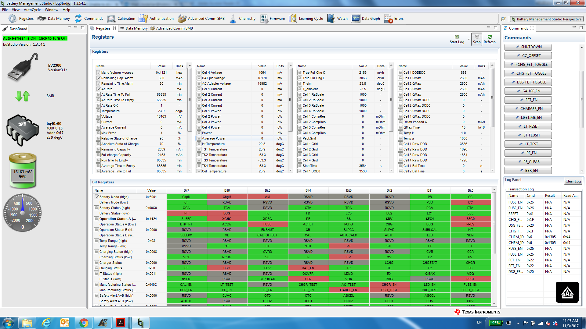
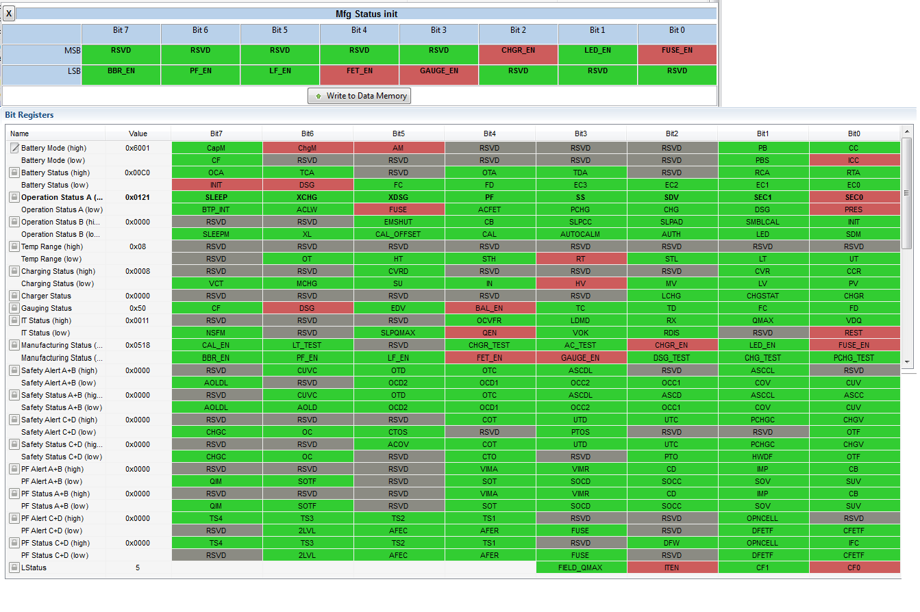
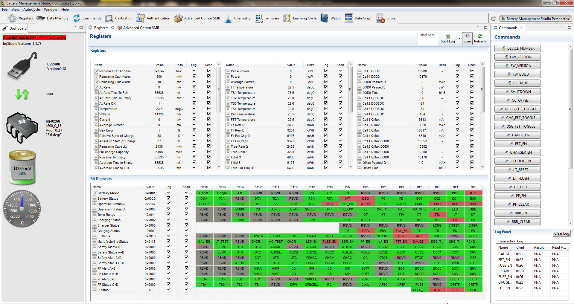
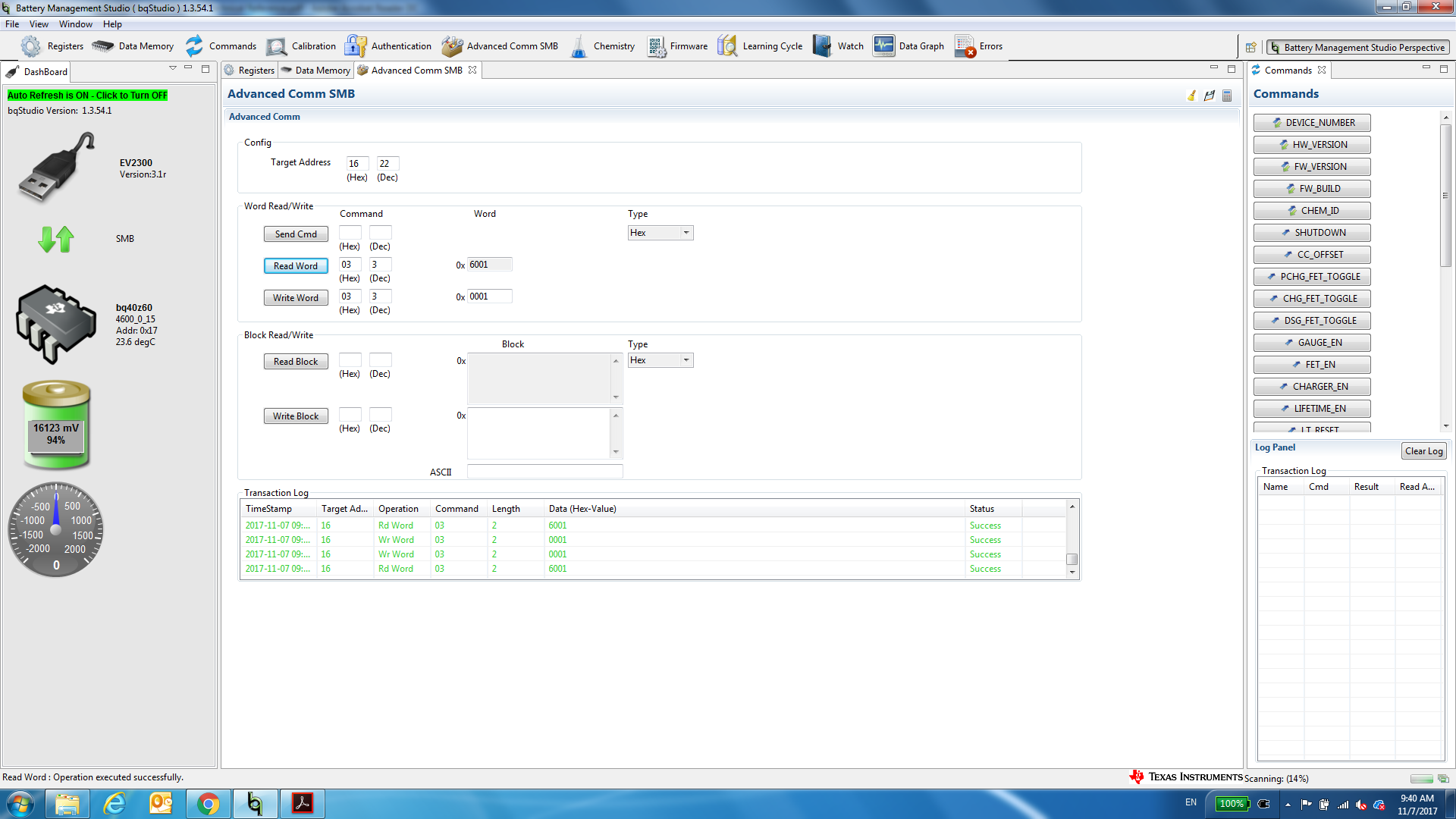
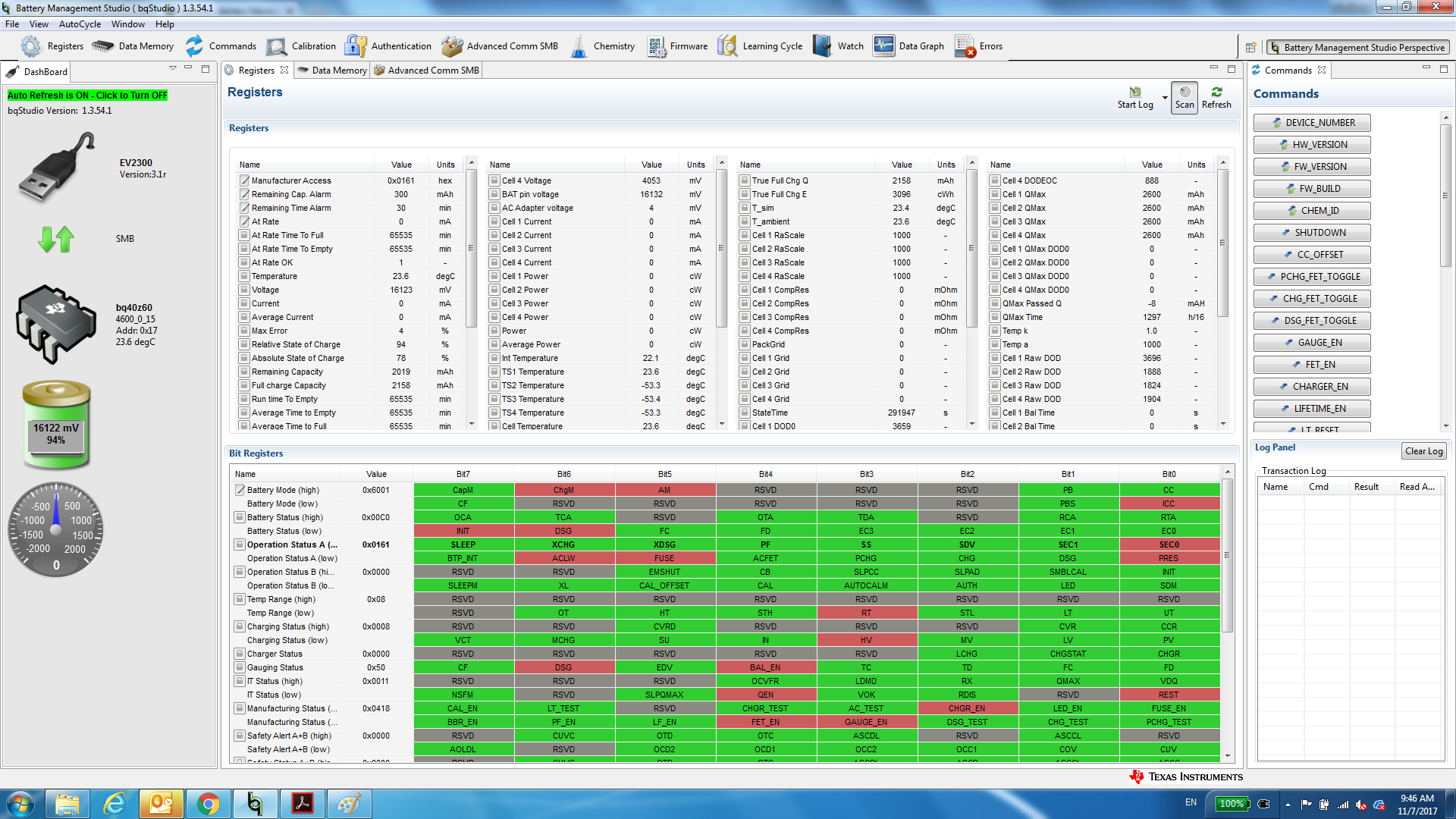
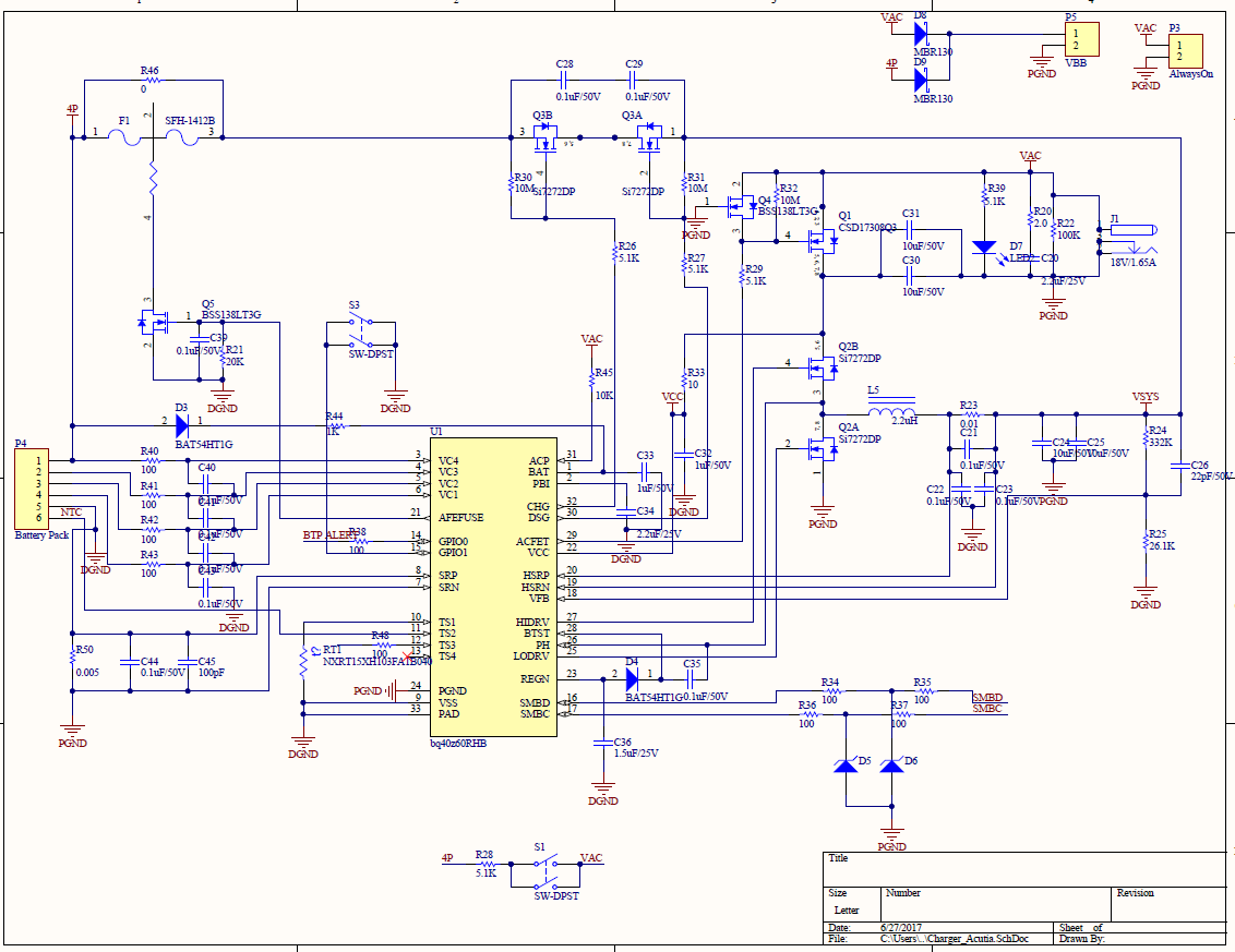
Currently, the output voltage is zero. If you look at the register status, FUSE is asserted, but the voltage of PIN 21 is 0. And it looks the DSG is enable, but the voltage of PIN30 is also zero(Source and Drain of Q3B are close to 16V).

BTW, in the schematic, I didn't solder the FUSE(F1). I used a ZERO resistor instead.

I also inculded the SREC file for your reference.unable to discharge_customized board.zip

Lian

  • Hi Lian,

    It looks like the CHG and DSG FETs might be off. Try clicking the FET_EN command button to see if that helps.

    Best Regards,

    Kevin
  • Hi Lian,
    In addition, Your fuse flag in operation status is set. Send the fuse toggle command (0x0001D) to clear it.
    thanks
    Onyx
  • Hi Onyx,

    I disabled FET_EN, and enabled DSG_FET. But the measured voltage of PIN30 is still 0.

    I also send COMMAND of 0x001D, and the bit of FUSE is still asserted. I sent a couple of times, no change of FUSE at all.

    Lian

  • Hi Lian,
    Your charge fet is still disabled. you have the xchg flag set. Your sniipet does not capture the safety status and alert regiters so one see if there is a safety status set.

    What do you have MfgStatusInit[FUSE_EN] set to ? You should sent command 0x0026 to allow the fw to take control of the fuse and then click the fet enable command button. See section 11.1.22.

    You need to make sure the fuse flag is clear in operation status register
    thanks
    Onyx
  • Hi Onyx,

    Here is the snapshot of my Manufacturing Status Init and the register status.

    No matter I enable or disable FUSE_EN, the bit of FUSE in the Operation Status A register seems SET all the time.

  • Hi Lian
    Your xdsg flag is now clear meaning you should be able to charge or discharge now. send your fet enable command so we see if the chg and dsg flags in operation status gets set. Also, can if you are using your board for this test, pull afefuse to vss so we see if that helps
    thanks
    Onyx
  • both XDSG and XCHG are disabled.

    First, the pin AFEFUSE is deasserted (0V) as I measured. Even if I pull the AFEFUSE low, it doesn't change anything.

    If you look at the register status of (DSG), it looks this pin 30 should have been enabled, but the measured voltage is still 0V. I guess the asserted bit of FUSE is blocking the DSG AND CHG FETS from functioning.

    Please advise.

    Lian

  • Hi Lian,

    The fuse flag being set is definitely what is preventing your charge and discharge fets from getting turned on. I tested the command 0x001D on my board and i am able to toggle the fuse flag on and off. When the fuse flag comes on the charge and discharge fet flags  goes off. See snippets. You need to write to gauge address 0x16. i see from your snippet you were writing to address 17.

    the one think i noticed that was diffent between your flags and mine was that you had the chgM and AM flags set. Try clearing those  and try again

  • Interestingly, I'm unable to change the value of battery mode(0x03) through SMB. The value is supposed to be 0x0001.

    As you see in the snapshot, I tried to write 0x0001 to the register of 0x03, it doesn't work (the read value is still 0x6001 after the writing command).

    I've tried both the address of 0x16 and 0x17, and seems both are able to communicate with the gauge.

    One thing I want to bring up. If I wirte 0x0000 to it, the value will be 0x6000. Therefore, I can change the LSB(the bit of ICC), but not the bits of ChgM and AM.

  • can you program your gauge with the default firmware on TI.com and then see if that fuse flag gets cleared

    thanks
    Onyx
  • Hi Onyx,

    I soldered another board. It seems the fuse is ok now. However, the device(bq40z60) heats up quickly when I plugged in the AC adaptor, and the internal temperature is around 63C as you've seen in the snapshot.

    Without the AC adaptor, the charger is able to output, and the Vsys is close the voltage of battery(~16V)

    Not sure what caused heat. We do design a pad to connect the chip pad and PCB to disapate the heat. But I have no idea why it's still very hot(I can feel it when I touch the chip).

    Compared my design with your EVM, the only difference comes from Q3 in the schematic(chg, dsg FETs). Instead of CSD17308Q3I replaced them with Si7272DP.  Q2 in the schematic is still CSD17308Q3.

    Thanks

  • I do not see any issues with your schematic. Does the copper pad under the bq40z60 provide a good thermal reservoir or just a small pad on the top level? You can reference the bq40z60EVM layers in the EVM User's Guide for guidance.
  • I think it makes sense. I did design a pad for heat dissapation, but it seems our technician forgot to solder it. I guess I need to rework on the soldering.

    It's fully functional now.

    One question, without the heat dissapation pad, the chip will heat up and possibly reach high temperature?

    Lian

  • The device does require heat transfer through the solder pad when using the charger due to switching losses to drive the charger FETs.