This thread has been locked.

If you have a related question, please click the "Ask a related question" button in the top right corner. The newly created question will be automatically linked to this question.

LM2576: LM2576-ADJ Spike issues

Part Number: LM2576

Hi,

We have 2 x LM2576-ADJ production 5.0V and 4.0V respectively. The average Load Current does not goes beyond 500mA.

5.0V supply goes to SoC and 4.0V supply goes to GPRS (2G) modem. GPRS modem requires a peak current of 2A and we have placed a 100uF tantalum capacitor close to Modem.

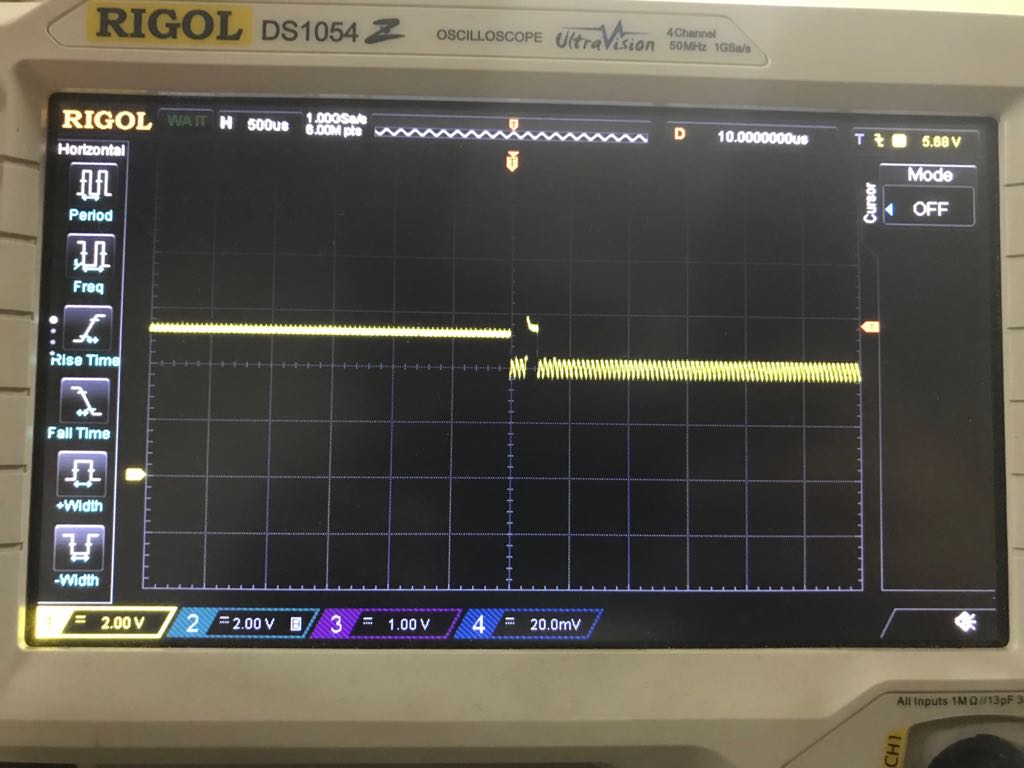
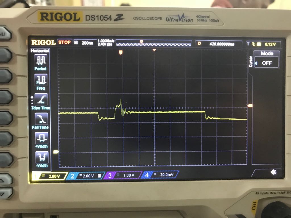
Now we are getting issues because occasionally we see that either SoC or Modem gets short circuited. We are assuming this is happening because of some spike at Power-up but we have no clue what is the reason. We suspected counterfeit product and ordered fresh material from Mouser, but still facing same issues. Another point of concern may be if the design is under-rated. But should that create voltage spikes high enough to damage the load devices?

Please find the schematic attached.

3301.PowerSupply.pdf

  • Hi,

    Do you have any scope capture maybe during load transient?
    Also, the layout of your PCB file?

    Thanks
    -Arief
  • Hi Arief

    Thanks for your reply.

    I don't have load transient off-hand. Can get it to you by Monday. In the meanwhile sharing the PCB Layout with you, if this of any help.

    Top Layer Layout

    Inline image 1
    Bottom Layer Layout
    Inline image 2
  • Hi Arief,

    Please find the Load Switching waveforms. 5V at 1.5A Load. I can see transients at Switch ON and OFF,.The Switch ON transient tend to go up to 6V and Switch OFF transient tend to go up to 10V for a few nanoseconds.

    Is the because of bad design or bad layout?

    01. Switch ON

    02. Switch Off

    04. Switch OFF - Zoomed

    03. Switch ON - Zoomed

  • Hi Arief,

    Do you have any suggestions for the same?

  • I am not exactly sure what the wave forms represent.  However, it looks like you may need more output capacitance if you are getting big output voltage spikes

    during a load transient.

    Also, I can not view the layout files you sent.

  • Hi Frank,

    Reattaching the layout files:

    Inline image 1

    Inline image 2

    Also please ignore the load transient waveforms shared earlier. We figured out later that the wiring was not proper and hence there were huge transients because of ground loops.  Please find the new waveforms below:

    Switch On Transient

    Switch Off Transient

  • For some reason I still can not view your layout file.

    However, based on your latest findings are the load transients OK ?

  • Ohh, not sure why is that. Were you able to see the Scope screenshots?

    We increased the Caps from 100uF to 400 uF (4 x 100uF) tantalum and observed that it has lowered the amplitude of spikes, which means: 

    1. We will have redesign the PCB

    2. Increase the Capacitors and may be inductor as per recommended by TI webench. 

    Although, at this point we are still not clear if it was these spikes that were causing the components failure at power up or something else. I think this may be a natural way to proceed is to fix what is broken first and then do further testing.

    Thanks a lot for your help.

  • Posting a final update on the same, may be it helps someone.

    Even after increasing the Caps to 400uF we could see issues, so we went back to design sheets to verify everything. Although the PCB layout is not ideal but after carefully evaluating we could see that the Input Cap, Switcher, Output Cap and Diode share a good solid ground. The Feedback was not in path on inductor flux.

    We could see the Switching frequency was not stable and was showing lot of noise. We increased the thickness of track from Inductor to Caps but no result.

    This made us to reevaluate the component values. Luckily we had a device with LM2576-5V. We put that to Load testing at 1.5A and the output was clean and switching frequency was also clean.

    We changed our inductor and capacitor to match the values. i.e. 100uH and almost 620uF caps (4x100uF Tantalum + 220uf Electrolytic) and voila it worked perfect. The switching frequency noise is gone.

    We will be testing further to observe any spikes but at this moment we are under the impression that spikes were resulting from undervalued components that lead to undesired loop in Switcher.