This thread has been locked.

If you have a related question, please click the "Ask a related question" button in the top right corner. The newly created question will be automatically linked to this question.

LM3409: LM3409MY/NOPB working on PWM?

Part Number: LM3409
Other Parts Discussed in Thread: LM3406

Hi,

I am writing this from a company in Germany. We are using LM3409MY/NOPB as a buck controller to supply output to LED. The PGATE of this IC connects with the gate pin of an external MOSFET.

The input we are using is 24V PWM. Frequency range is 100 to 1000 Hz. This same input is used for both the LM3409 ic as well as to power the MOSFET.

1) Do we need to use capacitor as a buffer to smooth the PWM input? Capacitor is used before the input is supplied to the IC and to the MOSFET.

2) Can LM3409MY/NOPB work fine for the PWM input I mentioned?

3) What can happen if the duty cycle of the PWM is too low? (or too high)

I look forward to response.

Thank You
AZ


  • Hello AZ,

    Are you saying that the input voltage is a square wave? Are you intending to dim it via the input voltage square wave duty cycle?

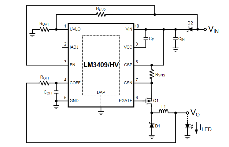
    If so you could connect the UVLO resistor network to the input voltage and use a schottky from the input voltage to the input capacitor. The VIN pin and the FET would then connect to the capacitor, the capacitor will hold up the voltage, and the UVLO will stop switching when the input voltage is low.

    The LM3406 is capable of less current (I am not sure how much you need) but it is also designed for applications like this.

    If I misunderstood how you are trying to drive the LM3409 please let me know. Thanks.

    Regards,

    Clint


  • Hello Clint,

    Thank you for your response.

    Can you please see the attached diagram, is that how you want it to be set up?

    Yes. In this diagram, the input voltage(before D2) is PWM.

    I am trying to drive LEDs requiring 1A.

    The LM3406 is providing less Imax because of the limitations of the internal circuitry of LM3406? Because as I understand, changing the value of Rsns should change the value of Imax, regardless of which IC we use.

    I look forward to your response.

    Regrads,
    AZ

  • Hello AZ,

    Yes, that is the correct way to connect it. The limitation on current for the LM3406 is simply because it is integrated so you need to set some current limit for protection. The LM3409 is a controller so you can size the switch for higher currents if desired. The LM3406 will not allow for peak switch currents over 2A (which is where the 1.5A average output current max comes from).

    Regards,

    Clint

  • Hey Clint,

    Thank you for a response. I have 3 questions.

    Suppose the frequency of the FET and inductor is f2. And suppose the frequency of PWM Vin, input voltage is  f1.

    1) What could be the range for the values of f2 to f1 ratio? I would like to know the minimum and maximum f2 we could use, considering that f1 in my case is 100 to 1000 Hz.

    2) What could be the most suitable value of f2 for EMC testing?

    3) What could be the most suitable value of f2 for the highest efficiency?

    I look forward to your response.

    Best regards,
    AZ

  • Hello AZ,

    100Hz to 1kHz isn't that fast for a part that responds so quickly. Still, the higher the f2 the better the linearity when dimming. Conversely the lower the f2 the better the efficiency. I would probably set it between 200kHz and 500kHz going towards the lower end if efficiency is of the most concern and towards the higher if you need a very wide dimming range with better linearity. Still, at the low f1 you are using the dimming should be very good at either end of f2.

    As for EMC it kind of depends on the app and the EMC requirements you are trying to pass. For example in automotive it is generally set around 350kHz to 390kHz because that keeps the fundamental out of the AM band and makes passing easier. But you should be able to filter the fundamental and harmonics sufficiently regardless.

    Regards,

    Clint