This thread has been locked.

If you have a related question, please click the "Ask a related question" button in the top right corner. The newly created question will be automatically linked to this question.

UCD90160A: UCD90160A 12V error message in standalone mode from PMON GUI

Part Number: UCD90160A

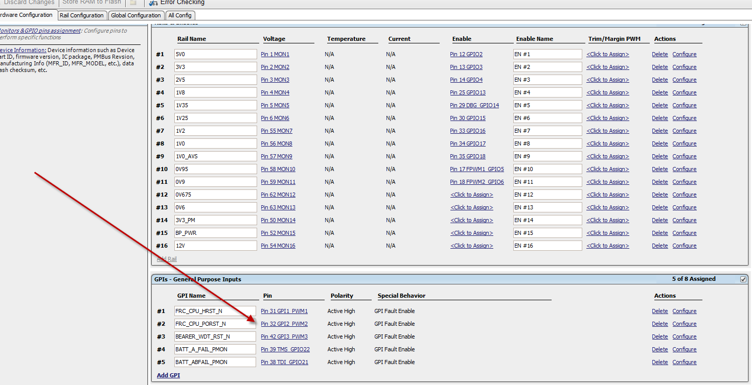
In the TI GUI, I get:

Rail #16: VOUT_MODE is set to 0x16 (exponent = -10, max voltage reading = 31.999V. 

VOUT_COMMAND is set to 12.000V, VOUT_SCALE_MONITOR is set to 0.167, VOUT_CAL_MONITOR is set to 0.000. 

Therefore the voltage reading might be overflow (71.856V) and reported as zero.

What is this about?

ANOTHER THING: the GUI in standalone mode gives an I2C address, which is not the one I am using by pin strapping, but how could it know this since standalone?

  • This is a known issue of GUI. Please ignore this.

    We will fix in the next release

    Regards

    Yihe

  • ANOTHER THING: the GUI in standalone mode gives an I2C address, which is not the one I am using by pin strapping, but how could it know this since standalone?
  • GUI will not use this address to talk to your device. it is just a reference.

    You can change the address if you prefer.

    Regards

    Yihe

  • OK, so I'll ignore this too.

    ANOTHER QUESTION: I need to have a hex file for the CM, but the GUI as far as I can tell doesn't give a hex file. How can I generate the hex file for the CM's BPWin 2800 programmer?

  • ANOTHER QUESTION: If the part is programmed with the wrong program, how can I re-program the part while it is on the board using the dongle? Can it be programmed while in reset to keep the power supply enables from going active?

    Additional clarification after receiving Anne Ngo77 email:

    I have a board coming back 1st prototype next week and I had the factory program the PMON UCD90160A device, but noticed I didn’t control one of the enable outputs, so need to change it before letting the board complete any power-ons.

    I don’t have the new hex file, and won’t have this in time, I have only what the standalone GUI gives me, the .xml file.

    I need to load the new .xml file to the PMON that is soldered to the board before it powers up the attached POLs improperly.

    If I hold the PMON in reset by grounding pin 9 of the UCD90160A, would that prevent the enable outputs from going active, and also would I be able to use the TI USB dongle to upload the new .xml file to the board’s UCD90160A while it is in reset?

  • The hex file is only available in online mode (live device is connected to the USB dongle). The option is in File menu -> Export..., then select "Data Flash File" tab
  • Not sure what you mean by "can it be programmed while in reset...". If you mean "re-program while device is monitoring...", then the data flash file (.hex format) can be used to program the device
  • I have a board coming back 1st prototype next week and I had the factory program the PMON UCD90160A device, but noticed I didn’t control one of the enable outputs, so need to change it before letting the board complete any power-ons.

    I don’t have the new hex file, and won’t have this in time, I have only what the standalone GUI gives me, the .xml file.

    I need to load the new .xml file to the PMON that is soldered to the board before it powers up the attached POLs improperly.

    If I hold the PMON in reset by grounding pin 9 of the UCD90160A, would that prevent the enable outputs from going active, and also would I be able to use the TI USB dongle to upload the new .xml file to the board’s UCD90160A while it is in reset?
  • By "pin 9 of UCD90160A", do you mean GPI #2 (Pin 32 GPI2 PWM2)? Which "enable outputs" you don't want to be active? In general, you would be able to use the TI USB dongle to program the UCD90160A using the .xml file. However, it also depends on the current configuration loaded on your device, the new configuration will be loaded on the device, and what you want to achieve.

  • Pin 9 is the reset and I don’t want pins 12,13,14,25,29,30,33,34,35,17,or 18 to go high until I can reprogram using the dongle, GUI, and .xml file.

  • When the UCD has no configuration, all IOs remain the same state as reset. PIN 17-24 are active output low and the rest IOs are Hi-Z. 

    Does this help?

    Regards

    Yihe


  • Another question. I have a small switching module to power the 3.3V PMon for normal operation, once I re-program the PMon with the dongle. Would the dongle 3.3V be OK with connecting with this during normal operation? I would like to leave the dongle on for monitoring voltages, etc. Or would the dongle's LDO cause trouble with the power? The main 3.3V power for the dongle is from a 0.6 Amp MPS  MPM3606 micro module.

  •  Another thing, I noticed the enables seem to be configured for active low. See enclosure for 1V8, typical of the others.

    Am I looking at this correctly? What should the settings be? Should they all be active high and Actively Driven (not tristate) ?

    I can change them all to active high, and save it, but when I repower, they come up active low again.  What's wrong? Are they active high even though they say active low?

  • Will you consider a jumper to separate two power source?

    Regards

    Yihe

  • Please refer your power supply data sheet to see which control signal is required?

    Did you click store ram to flash buttom before you power cycle the board?
    Regards
    Yihe
  • OK, thanks for the advice.

    I have another question. Is the a way to get pin 38 and pin 39 to be stored in the NVM fault log? See enclosure.

    Also, how do I enable fault logging on power fail? I have the hold-up capacitors.

  • Also, which pins are GPI5, GPI6, GPI7, and GPI8? I only see GPI1-4 on my schematic, given earlier.
    But I see GPI1-8 in the GUI Global Configuration tab.
  • Yes, the changes of GPI can be stored into the non volatile memory.
    Please refer section 4.3.1.1.2 at www.ti.com/.../slvub51.pdf for how to enable GPI logging.
    please refer section 4.3.1.3.1 at www.ti.com/.../slvub51.pdf for how to enable particular event logging.
    if you have the brownout circuity, please follow 4.3.1.3.2 to enable the brownout logging.

    Regards
    Yihe
  • The GPI1-8 are the index configured GPIs, it is not associated with any fixed IO. you can assigned any particular IO to GPI1-8.
    Hope this helps.
    Please create new post for each individual question so that other people can benefit from it.
    thanks
    Yihe