This thread has been locked.

If you have a related question, please click the "Ask a related question" button in the top right corner. The newly created question will be automatically linked to this question.

TPS62150: TPS62150 is failing without apparent reason

Part Number: TPS62150
Other Parts Discussed in Thread: LMH6518, TPS65131

Hi,

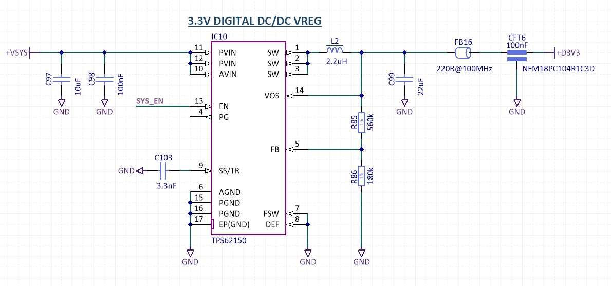
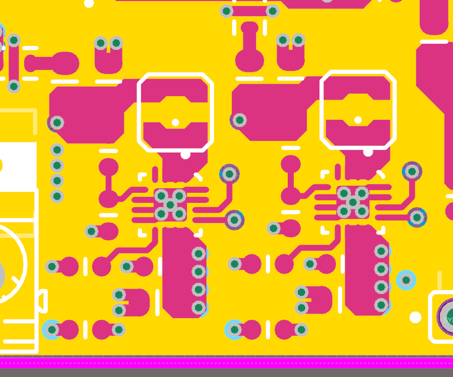
I encountered unexpected problem with TPS62150 converter IC. I have soldered two boards, both with two DC/DC based on this chips and all four IC's have burned while only one managed to work properly for a while. On first board both simply never started to work, while on second board only one worked (and, actually, for brief moment were performing very well). Most of them simply stopped to respond having 0V on output (and VIN on SoftStart capacitor), while one attempted to work, but outputed completely nonsense waveforms and caused coil to audibly buzz. This last one showed short-circuit on output even when was disconnected from rest of the circuitry, and more interestingly, it done so only when soldered on PCB - after desoldering it I could not measure anything abnormal either on board, or on the very chip. I resoldered  the working one in his place to check if it will persist, but this chip simply ceased to work at all (without showing any voltage or short-circuit on output).

The parts have been hand soldered, however, no other IC's on board showed any kind of damage (like, for example LMH6518 with I think is much more delicate), so I don't suspect that issue was caused by ESD or overheating. Also, i tested everything with regulated linear power supply that doesn't generate any spikes or excess HF ripple. Below are schematic and layout screenshots:

I never have similar problems before, even with other Texas DC/DC's like TPS65131. Have You any suggestion what might be a cause of this problem? Are those parts exceptionally susceptible or ESD or thermal damage and I should take additional precautions handling them?

Best regards

  • Hello,

    can you please check our PCB layout recommendations in the data sheet.
    It is recommended to have a GND plane on the top layer and the input and output caps are placed close to the IC as shown in the drawing in the data sheet. Please also check FB and VOS pin routing
    Best regards,
    Ivo

    Texas Instruments
  • Hi,

    I strongly doubt that is a layout fault, I have layed out smiliar DC/DC's many time before, often switching larger currents with larger frequency, and they never experienced any problems. To being honest - those are first DC/DC that I ever killed. Also, the one TPS62150 that was working wasn't showing on scope anything abnormal - stable voltage, small ripple, no excess spikes and ringing on switching node. It failed after swapping him with failed one, to eliminate possibility of manufacturing fault in PCB. I suspect that those chips develop fault during soldering, similar to this: https://e2e.ti.com/support/power_management/non-isolated_dcdc/f/196/p/506075/1834887

    I am going to order automotive grade version, they should be more rugged. If they survive soldering I will thoroughly measure whole converter for signs of anything abnormal. Unfortunately, i have not saved measurements of surviving TPS before it died.

  • Hi,
    I agree that it is possible the device got damaged by manual soldering by hand. (temperature profile, ESD, but maybe more likely solder shorts). This is difficult to check from my end. If the device is soldered properly there should not be any issue.
    In our experience a lot of failures are related to over voltage spikes caused by parasitics on the PCB. Therefore we recommend to follow our layout recommendations.
    Best regards,
    Ivo
  • Hi, thanks for response
    I will try with new IC's and share the results. If they'll work, I will make any necessary measurements.

    Best regards