This thread has been locked.

If you have a related question, please click the "Ask a related question" button in the top right corner. The newly created question will be automatically linked to this question.

BQ40Z60: Enabling CHG, DSG FET

Part Number: BQ40Z60
Other Parts Discussed in Thread: EV2400, BQSTUDIO

Hi there,

I have built a "custom" PCB which is at the moment nearly identical to the EVM. Therefore mosfet T8 and T10 are not soldered. The load is connected to "BUCK-VOUT(VSYS in EVM)" and a power supply is connected to "VCC_Supply(VAC in EVM)". So the setup is in my opionion the same as described in your EVM-Guide "SLUUB71".

Setup:

DC-Input: 16V

Battery: 2 Li-ION Cells (2s1p) permanently attached

EV2400

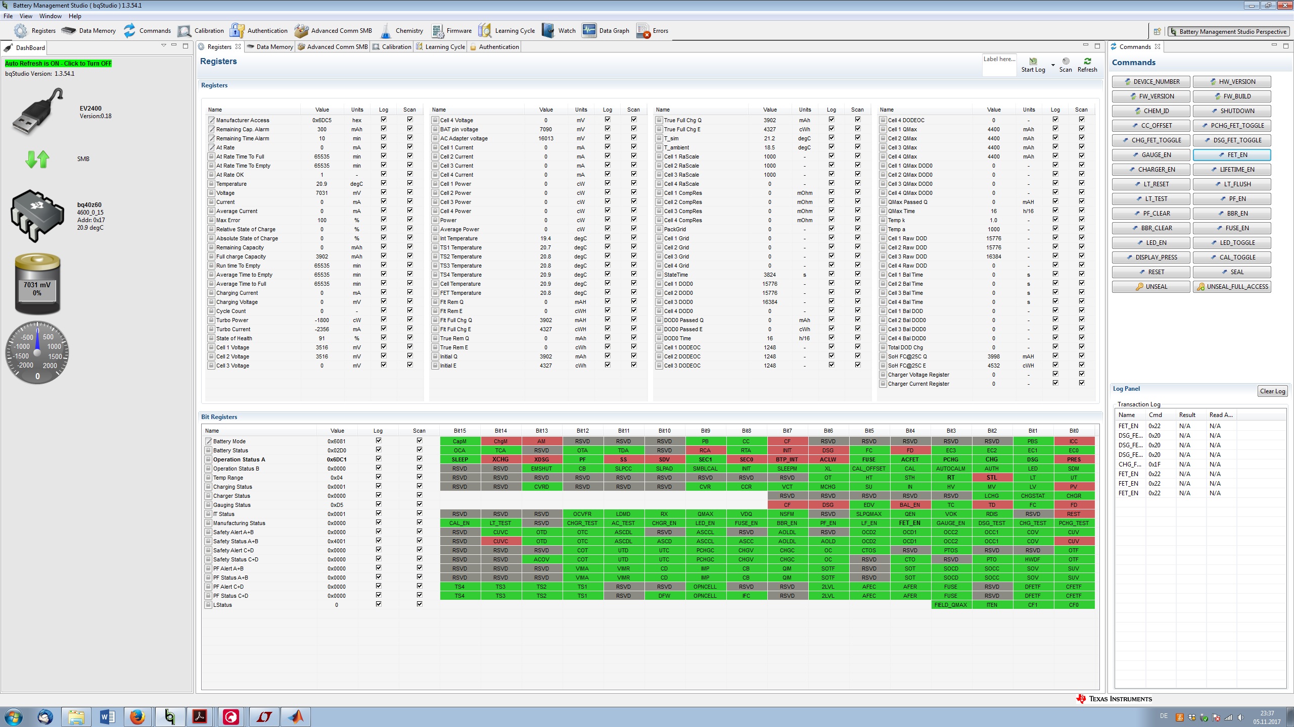
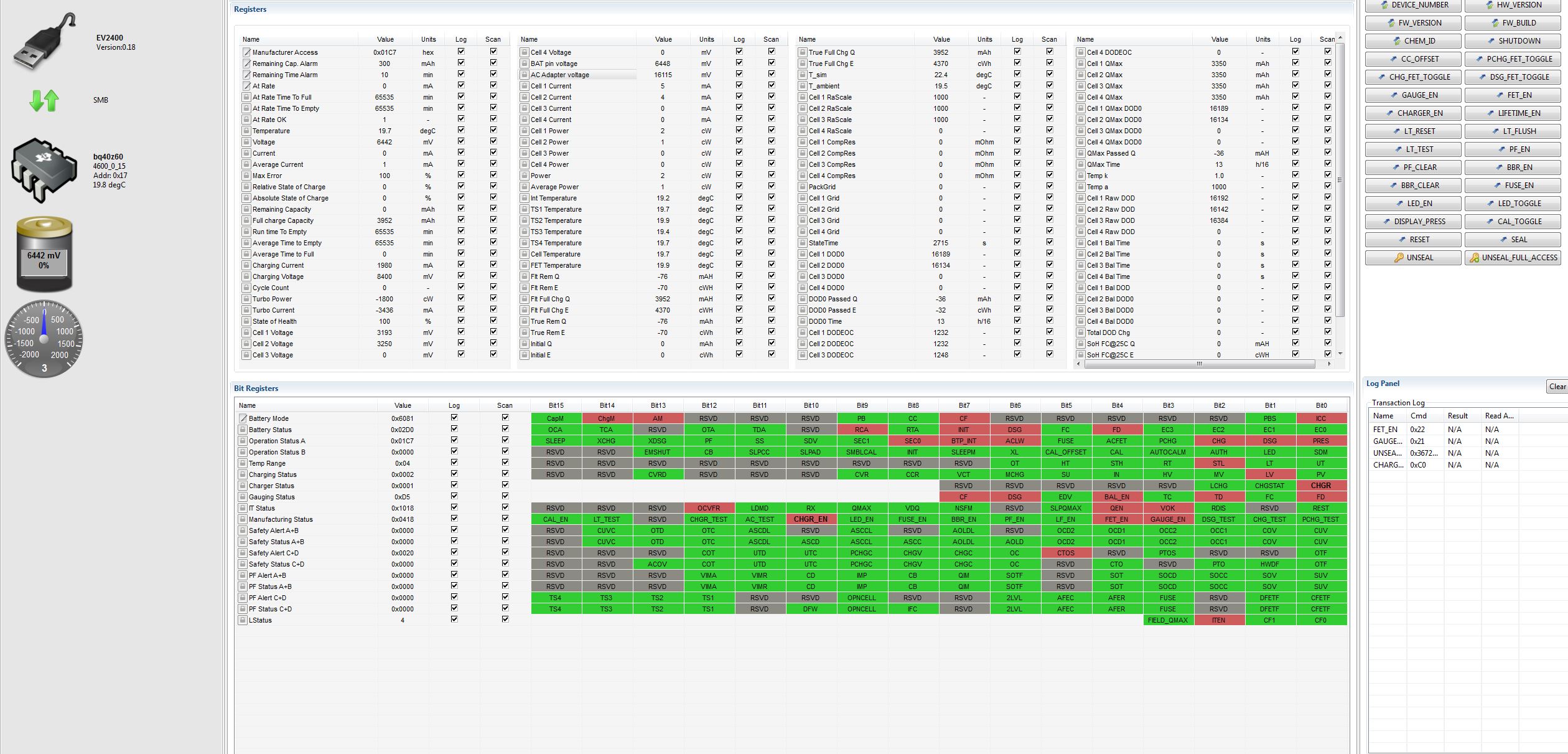
My problem is, that it seems like I do not know how to adjust the registers properly.

What I did so far:

- I checked the MSB register for the proper cell number configuration. Last two bits are [0 : 1] According 12.2.3 in sluaa04d this should be 2 cells. (Red is 0?)

- What do I have to do with the NR bit?

- Should FET_EN turn on the DSG and the CHG Fet? When I use the FET_EN command I see at the gate of CHG 3.7V and 0V at the DSG Pin. When I turn of the "FET_EN" I have 16,3V at the CHG Pin and around 0,5V at the DSG Pin. Seems to be wrong to me.

- AFEFUSE (PIN 21) is pulled to GND (I've read that this could be a problem), Alert (PIN 14) I pulled also down, LED Display (PIN15) is 5V

Questions came up:

- Do I need to do a learning cycle before I see a fuel level in the DashBoard? I cannot do this as I get no voltage at VSYS.

- both XCHG and XDSG are not set in my case. Should be both set (green) or not set (red)?

- Do you maybe see a obvious mistake I've not realized?

I've added my schematic and a screenshot of my bqstudio register setting. If you need any additional information let me know.

Best regards,

Thank

you very much
Thomas

  • Hi Thomas,

    The technical reference manual address most of your questions. I would encourage you to always search for answers to you questions in the TRM. I will attempt to address your questions based off the TRM..

    -for 2s only cc0 needs to be set.

    -For the NR bit it depends on if your battery is detachable or not. If your battery isn't detable then pull pres pin to ground and have the NR flag set. If it is detacheable, then clear the NR flag.

    - Fet enable turns on the charge and discharge fets. and sending the command again will turn them off. From your snipped i see that you have the CUVC flag set.  Meaning you have an undervoltage condition hence the discharge fet being turned off. You need to set the number of cells in series correctly like i explained above and then make sure your battery isn't experiencing any safety condition that will cause the fets to turn off

     -If the Afefuse pin is not used, it should be pulled to ground. See data sheet and EVM reference schematic and user guide  for further details

    -Yes, you need to do a learning cycle. Pls follow app not below on how to carry out a learning cycle. you have to have the charge and discharge fet turned on to carry out a learning cycle. you have the cuvc safter status flag set. That needs to be clear to be able to carry out a learning cycle.

    www.ti.com/.../slua777

    thanks

    Onyx

  • Hey Onyx,

    it was really the wrong adjustment of the cell number. Now I can enable the Fets and have power at the output. Discharging at the moment. I am going to do more testing tomorrow like charging. I'll let you know whether everything is working.

    Thank you very much so far. Classic osi layer 8 problem :-)

    I would like to just use a 2 Pin connector for charging and discharging (I am not planing to do both at the same time) .Therefore are the mosfets T8 and T10. They are controlled by the ACFET. I would measure the "Kontakt+" voltage via the VCC Pin and using the comparator VCC/HSRN. So if VCC > HSRN  T8 is conducting, if VCC < HSRN T10 is conducting. Should work, right?

    Best regards,

    Thomas

  • Hi Thomas
    I am not sure i follow your description. However, the proof of the pudding is in the eating. Run your test and see if it works.
    thanks
    Onyx
  •  Hi Onyx,

     I did a few tests the last few days but I am still not able to get it to work as wished.

    Just short question concerning the learning cycle. What is the correct intial condition of the bits when starting the learning cycle (first time discharging)

    I'd say QEN set, VOK set and RDIS also set. But I think those bits are toggled when I start the learning cycle. Is there a way to set RDIS separatly from the others? I guess the command x0021 and x0041 kind of doing the trick.

    I'd would be great if you can tell me what the initial condition before pressing the "start" button should look like.

    And another very simple question. In the calibration section there is "Applied Battery Voltage" and "Applied Pack Voltage". The "Applied Pack Voltage" is the voltage of the AC Adaptor? So VAC to PGND and not VSYS to PGND as written in sluub71 (3.3.1)? I am still seeing the ACLW pin toggling although the ACP Voltage is way above the Battery Pack voltage.

    And last but not least. I cannot get the device to charge anymore. I've added a screenshot below. Any idea?

    Thanks a lot

    Best regards

    Thomas