This thread has been locked.

If you have a related question, please click the "Ask a related question" button in the top right corner. The newly created question will be automatically linked to this question.

TPS62092: Vout failing to reach required level, power good staying off, possible charge pump issue

Part Number: TPS62092

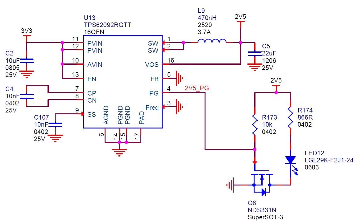
I'm currently using a TPS62092RGTT, 2.5V regulator on a board we've designed.  We’ve made quite a few boards and on a small handful, from different batches we are seeing the same problem, the regulator fails to regulate correctly (reach its required output voltage).  Often it does this from start up but occasionally it stops regulating after its been running a while quite happily.


The behaviour we see is the power good line drops low and the regulator output falls to about 2V (it is meant to be 2.5V), we’ve checked the connections all around the device, there’s no shorts on the output, it’s not pulling lots of current,  the devices on the output rail are actually still working correctly, the only thing we have noticed is when its working correctly the Charge pump capacitor has 2.5V on one end and higher (~6V I think) on the other and when its not working it has 3.3V (our Vin) on both ends.  From this we’ve come to the conclusion its something to do with the charge pump circuitry and when its not charging up properly the output gate driver is not high enough to give us our required Vout, hence why its sitting at 2V not 2.5V.


On one of the faulty boards I’ve tried reflowing the capacitor and even replaced it, which temporarily seemed to fix it the issue but it is now back to being temperamental.  There seems to be no reason for when it does / doesn’t work,  we’ve tried hot / cold starts etc, it just seems to be sporadic, sometimes working reliably for days, sometimes repeatedly failing for days.


Any ideas as to what could be causing this behaviour, are our guesses about the charge pump being the issue correct and if so what could be causing it to not charge?

Thanks,

  • Hi Bryn,

    Can you share your schematic, PCB layout, and waveforms (Vin, Vout, SW, CP) when it is not outputting the correct voltage? What part number do you use for the charge pump cap?

    There are no known issues with this cap or charge pump, so we need to look at your specific design. It sounds like a board isn't 'broken' or 'good' but varies from time to time (power up to power up)? i.e. a board which has shown this issue will sometimes work normally later on?

    Do you have an EVM on hand to test out one of your devices on?
  • Hi Chris,

    Thanks for the reply.  Section of the schematics relating to the regulator should be below:

    The component list for all drawn is:

    U13                     TI                  TPS62092RGTT
    C2        10uF       TDK              C2012X5R1E106K125AB
    C4        10nF       TDK              CGA2B2X7R1E103K050BA
    C107    10nF       TDK              CGA2B2X7R1E103K050BA
    L9         470nH    TOKO           1239AS-H-R47M
    C5         22uF      Murata          GRM31CR61E226KE15L
    R173     10k         Panasonic    ERJ2RKF1002X
    R174     866R      Panasonic    ERJ2RKF8660X
    LED12                 Osram          LGL29K-F2J1-24
    Q8                       Fairchild       NDS331N

    When our layout guy gets time I'll get him to screenshot the relevant section of the layout and add that.

    When the board next stops working I'll see if we can capture some waveforms of the in / out / SW and CP pins.

    I would say the broken or good thing is not quite true.  Some boards (in fact most) are "good" and we have never seen this error on many hours of running and many power cycles, a few are "broken" and exhibit this behaviour, however the behaviour varies from time to time, i.e. it can work happily for a few days and then could not work at all for a few days, or it may take 4 or 5 power on attempts but then works fine, but as I say this behaviour is limited to a couple of units.

    No we don't have an EVM on hand.

    Thanks,

    Bryn

  • Thanks for sharing. Yes, PCB layout and waveforms are needed.
  • PCB layouts, of top metal:

    3.3V inner plane:

    And 2.5V inner plane:

    I'll attempt to capture some waveforms next time the regulator goes wrong.

    Cheers,

    Bryn

  • Thanks for sharing the layout. There are significant improvements that need to be made on the next board spin to get it looking closer to the example in the D/S (Figure 29).

    The input and output cap GNDs need to connect directly to the PGND pins. As well, the inductor should connect to the output cap right next to it without vias.

    You might try adding some metal from the GND plane above the IC to the 2 PGND pins. As well, add a small ~4.7uF output cap from the inductor to the PGND pins (just place the cap above the IC) and add a thicker bus bar wire to connect the inductor the the bigger output cap right next to it.
  • Hi Chris,

    Thanks for the feedback on the layout.  Do any of the issues you noted explain the behaviour we are observing?

    The 4.7uF output cap, what is this for, I couldn't find any mention of it in the data sheet, and when you say from the inductor do you mean the regulator side of the inductor, i.e. the SW output pins, or the cap side of the inductor, i.e. in parallel with the existing output cap?

    Cheers,

    Bryn

  • Yes, layout can make DC/DCs operate differently.

    The 4.7uF cap is just to get a small size (0402) cap where it should be in your layout. It would go from Vout at the inductor to the PGND pins. This is where the 22uF output cap should be.
  • Hi Bryn,

    Were you able to capture the issue with the extra cap installed?
  • Hi Chris,

    I've finally managed to get a board returned which has a regulator which consistently exhibits the faulty behaviour, enough so I can capture some waveforms.

    When i first powered it on the regulator seemed to start normally, then after about 30 seconds it went off, then it went through a phase of every power cycle lasting about a second then switching off, including one time I saw the power good bounce up and down many times then settle to off, and now whenever I power cycle it never starts.

    In all the plots below trace 1 (the yellow) is the board that is not working and trace 2 (the blue) is an example board that works perfectly and always has.

    The first plot is the input pin to the device (actually on the positive side of the input cap).  As you can see both are sitting at 3.3 V.

    The next capture is on the output pin of the device (actually on the input side of the output inductor).  As you can see the working one is switching normally, the non working one not, and I had to wait a fair while (10's of seconds) to capture it actually switch, normally it just sits there at about a constant 0.5 V ish.  If i probe the output side of the inductor on the working one I see a constant 2.5 V no switching, and on the broken one the same as the input, so 0.5 V no switching.

    I now moved onto looking at the charge pump, the negative side looks like this:

    And the positive side looks like this:

    As you can see the working board seems to be charging up the one side of the cap, while the non working regulator just seemd to be putting Vin on the positive side, hence why I thought my issue may be with the charge pump circuitry.

    Have you got any ideas, is there anything else you'd like me to capture before I start trying to tack extra components on the board.

    Thanks,

    Bryn

  • Hi Bryn,

    Thanks for the update.

    I expect that this failing device is damaged already. Do the CP/CN pins ever switch? For example, can you trigger on SW and see if CP/CN do anything when there is that single SW pulse?

    After that, you could add the caps and see if it helps. Assuming it does not, I would recommend removing this IC and installing it on an EVM. Then, take a new IC and put it on your board. Now, your board should work fine and we can debug the failing IC on the EVM.
  • Hi Chris,

    Quick status update, just before COP last night as it wasn't working I thought i'd just have a probe around the other pins on the device and see if anything else looked weird.  So I checked the Soft Start (SS) pin, it was at pretty well ground, zooming in greatly, you could occasionally see it attempt to ramp, incredibly slowly and only up to a few 100's of mV, before giving up.  I'm guessing this could explain the behaviour we were seeing on output as effectively this is holding the device off and occasionally attempting to start turning on then stopping.

    I checked the resistance between this pin and ground, on a working board its in excess of 3 MOhm, on the not working board it was more like 800 ohms, so low there's no way the current out of the charge pin would ever turn it on, which was weird because as I said I'd seen it work earlier in the day.  So assuming something may have warmed up and caused a 'short' I powered it off and left it over night, I rechecked the resistance this morning and it was approximately 80 kOhms, I powered it on, it refused to start, so I rechecked the resistance and it was back to 800 Ohms.

    I've since then popped off the SS capacitor, the soldering / footprints etc all looked fine and I've just checked the resistance of the cap in isolation which is reading open, so I'm doubtful there was anything wrong with the cap (plus we've just previously had it replaced).  But i've left the cap off so the pin is now unconnected, the resistance is now reading just over 1 MOhm and it seems to be working fine again.

    Any idea what the resistance to GND of that pin should be with nothing on it, and is there some spec we missed on the soft start cap that's important for correct operation, i.e. something that could be causing an issue with the internal circuitry when our cap is fitted?

    Regards,

    Bryn

  • Thanks for the update.

    Yes, if SS can't generate a voltage, then the IC won't try and deliver the output voltage and therefore won't switch.

    Have you visually checked the SS pin and area around it for solder shorts, etc.?

    A 10 nF SS cap is the standard value and is ok.

    You might try reflowing the IC or transferring it to an EVM to debug by itself.
  • Hi Chris,

    So with no SS cap attached I thought it was fixed, it ran fine for about 2 weeks solid and then I started noticing the power good, flashing on and off, then occasionally staying off for a bit then fixing itself, it is very sporadic and only seems to be off for 30 seconds or so, but it does keep doing it.  In one of its broken periods I managed to capture the following waveform of the SS pin on the device:

    Bearing in mind there is no cap on this pin anymore, it is completely open, this is a bit peculiar.  It looks quite a repetitive waveform, I wondered if there was anything you could glean from the on / off rate to indicate what the module actually thinks it is doing?

    Cheers,

    Bryn

  • No, that frequency does not tell anything. I suspect that this device is damaged.