This thread has been locked.

If you have a related question, please click the "Ask a related question" button in the top right corner. The newly created question will be automatically linked to this question.

TPS53318: TPS53318 shuts off under load

Part Number: TPS53318
Other Parts Discussed in Thread: TPS53319, TPS53319EVM-136

Hello,

I'm using TPS53318 for 5V power supply. Vin 5-22V, Vout 5V, Iout 5A max, 2.5A typ.

Design is based on webench and TPS53318 datasheet. ROVP is floating, I'm using only ceramic capacitors.

Problem:
Without load: for Vin 6-22V, Vout is stable at ~5.1V.
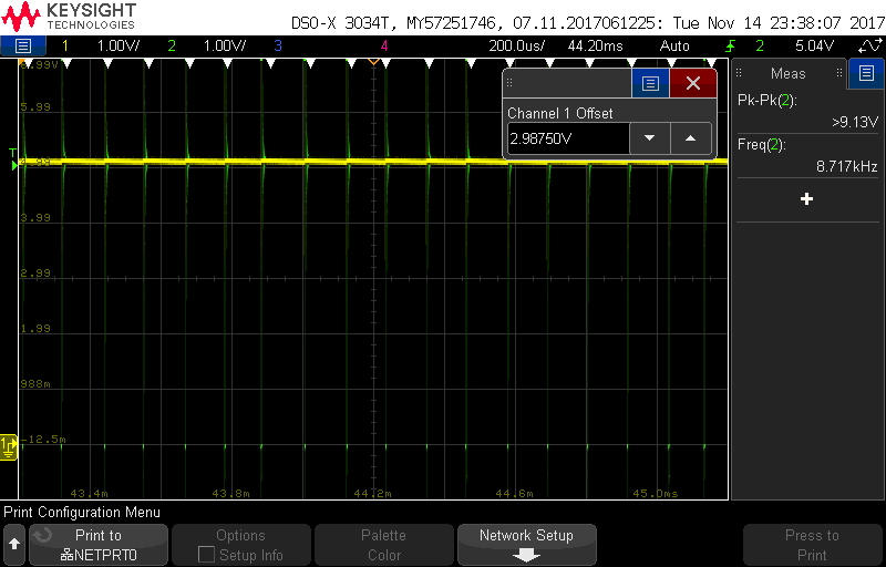
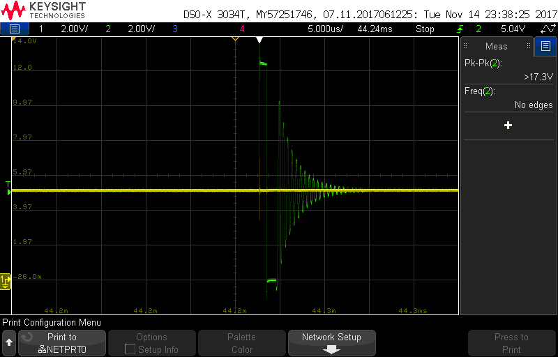
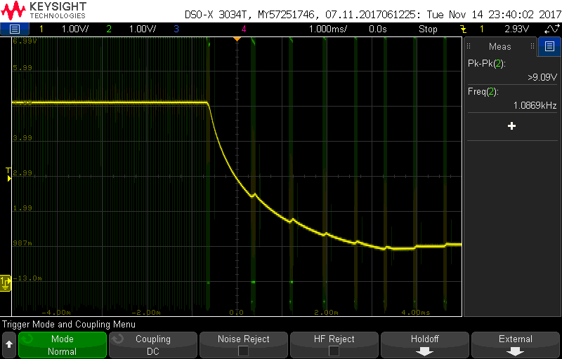
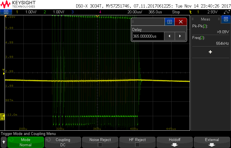
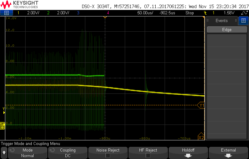
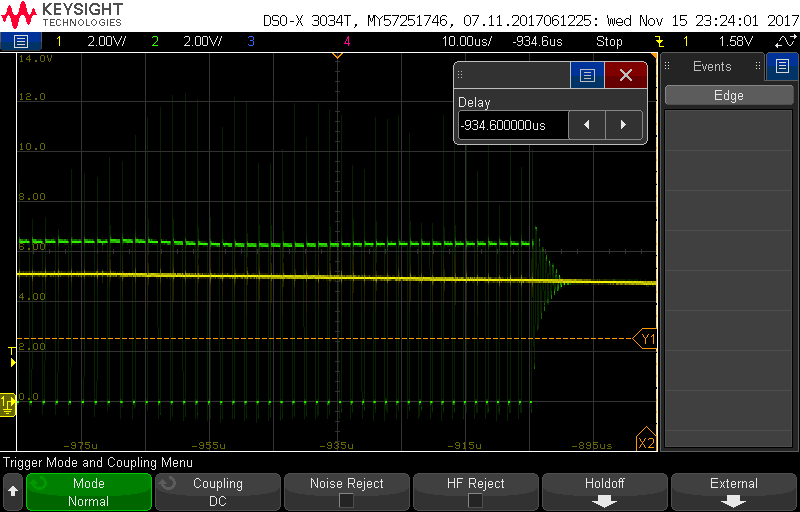
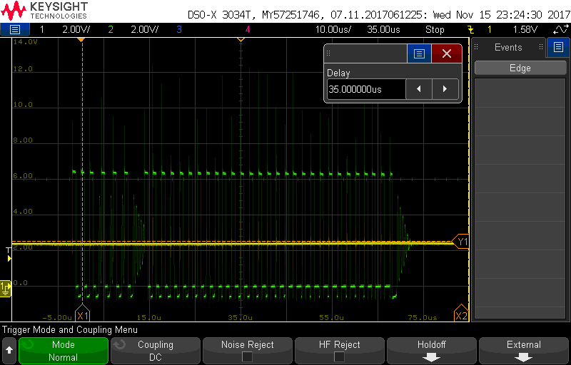
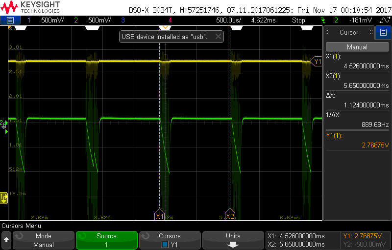
With load up to ~1.4A and Vin > 5.3V, Vout turns off. Vout restores immidiately when load is removed. It is not caused by bench power supply current limit.
With higher load, over 1.4A, Vout shuts off at any Vin.

Could you recommend changes with my design? Schematic attached.

Inductor: Wurth 4.7u 744311470
Input caps: 3x 4.7u 25V Samsung CL31B475KAHNNNE
Output caps: 3x 100u 6.3V Samsung CL31A107MQHNNNE

Thanks,
Tomasz

  • First off, you cannot use TPS53318 to generate 5 V output from an input range of 5 to 22 V. at an input voltage of 5.3 V, the output voltage will be around 4.24 V at no load. Adding load will decrease the output further, so I think that most likely you are entering under voltage protection, which latches both high and low side FET off. The TPS53318 will enter hiccup mode restart, but will not successfully do so until the load is reduced and or the input voltage is increased above about 6.25 V. If it is shutting off at higher input voltages at currents above 1.4 A, then you may have a layout issue as well. Can we see your PCB layout?
  • Hello John,

    You are right, with Vin at 5.1V, Vout is 4.1V, with 6.3V Vin, Vout is exactly 5V.

    To clarify:
    With no load (only status LED) Vout is 5-5.1V for Vin 6.3 - 22V.
    Below Vin 5.3V, Vout drops under load to about 3.5V, load higher than 1.4A shuts off output (not precise, tested with bunch of resistors), it recovers after load is removed.
    Above Vin 5.3V any load shuts off output, it recovers after load is removed.
    Above Vin 9.8V any load shuts out output, it does not recover until power cycle.

    Below are screencaps with layout. I also attached pdf with assembly.

    Assembly.PDFThanks,

    Tomasz

  • The board looks pretty small. Is the IC getting hot? Could be thermal shutdown.
  • No, it's not hot. Also, this shutdown happens instantly, I think that for thermal protection there would be some delay.

  • I suppose we will have to see some waveforms to determine what is actually happening.  We can start with Vout ans SW.  As usual it will probably take some time to troubleshoot over the forum.  If you observe any other waveforms which look suspicious, please include them.

  • Waveforms are included below.

    SW: green
    Vout: yellow

    No load, Vin = 6.4V
    scope_1

    scope_2 (zoom of scope_1)

    No load, Vin = 12V
    scope_3

    scope_4 (zoom of scope_3)

    Shutdown, 0.2A load, Vin = 7V
    scope_5

    scope_6 (zoom of scope_5)

    scope_7 (zoom of scope_5)

    scope_8 (zoom of scope_5)

    Shutdown, 0.2A load, Vin = 12V
    scope_9

    Thanks,

    Tomasz

  • Can you zoom into pic 5 as shown in red?  Make sure the amplitude is such that I can see the full SW node amplitude and the time scale such that I can see and measure the on and off times.  You can take a couple at different time scales.  Just to be clear you have the supply up and operating at light or no load and then when you increase  the load current it drops out?  One thing you can quickly check is your ILIM component value and soldering connection.

  • Could you clarify, which part of scope_5 should I zoom into? I did not save this waveform, but can recreate a similar one. 

  • Looks like I neglected to include the annotated screen shot. Unfortunately it is 2:20 am and I am not in the office ( I should be sleeping....) . I would like to see the point in scope 5 where the output initially starts to drop. I would like to see a few switching pulses prior and then the rest of the burst before switching stops. I need to see the full amplitude of the SW waveform.

    Thanks,
  • Yes, with no load/light load I have 5V output, which shuts off when I increase load.

    I did solder another board today, this time with 100k RTRIP - output still shuts off. I did not find any shorts / cold joints on neither board.

    Below are the waveforms you asked for.

    Vin = 6.4V, Vout = 5V, tried 0.2A load

    Thanks,

    Tomasz

  • There are 4 different protection mechanisms that cab=n cause the device to shut down ( 5 if you include thermal OTP, but we think we have eliminated that).
    UVLO is checked at VREG. You can check that it is not dropping out.

    You have EN tied to VIN. VIN is definitely dropping prior to the Vout drop out. You can try adjusting the threshold downward.

    Vout is definitely decreasing, but it appears it is not falling to the maximum UVP level of 75%.

    Current limit may not be accurate at duty cycles greater than 45 %. If you increase the input voltage up to 20 V, how much current can you draw?

    Vin is definitely drooping, Are you sure your VIN supply is not limited? Do you have a long cable connecting it? You can try 100 uF electrolytic in parallel with the input capacitors.
  • Below are VIN, VREG and Enable signals after adding load, there is definately voltage drop on VREG.

    green: VIN
    yellow: VREG
    blue: enable

    After VREG capacitor was changed to 4.7uF, shutdown happens at 6V Vin instead of 5.3V.
    Tried with 100uF and 470uF cap at Vin, shutdown still occurs. Same with another regulated power supply and 12V/3A brick.

    Thanks,
    Tomasz

  • If I am seeing this correctly it looks like your EN is dropping out. Can you try tying EN directly to a 3.3 or 5V source?
  • I have replaced resistor on voltage divider (R23=72k, instead 33k). Enable pin is now at over 2.5V (I will watch not to exceed 6V).
    It did not fix the problem. However, I did notice that these voltage drops on VREG occur periodicaly.

    I think that LDO should always be enabled if VIN is over 2V (8.3.1 - SLUSAY8E). Maybe these voltage drops are signs of LDO overcurrent?

    green: VREG

    yellow: enable

    Thanks,

    Tomasz

  • I've tested it, with enable pin pulled down VREG is still on.

    Under load, VREG has periodic voltage drops (as shown in my last post). Maybe these drops trigger e.g. overvoltage protection?
    As LDO is basically always on (above 2V), these drops could be caused by LDO overcurrent.

    Screencaps in my last post were taken with 4.7uF capacitor on VREG.

    I also tried different RF and MODE configurations - no significant changes.
    Vout was lowered to ~4.8V (100k/15k).

    Thanks,
    Tomasz

  • How many boards out of how many total show this? I will try to pull in some additional resources after the holiday to support this.
  • I have two soldered boards, both have the same problem.

    I have ordered more ICs, inductors (4.7u and 3.3u) and output capacitors (recommended by webench) from Farnell. I will solder another PCBs when these components arrive.

    We plan to order 200 pcs as soon as possible, although I may make some layout changes if required.

    Thanks,
    Tomasz

  • I'm going to discuss your issue with others on our team today or tomorrow, depending on availability. I'll let you know what we find. I can tell you that many other users are not seeing this issue.
  • Hello,

    Is there any local capacitor at VDD pin (4.7uF). This VDD pin supplies the input to the VREG. Also, please tie ROVP to GND. Please see this section on the datasheet.

  • Yes, initially there was 1uF capacitor. I replaced it with 4.7u some time ago, it did not fix the problem.
    ROVP has internal pulldown, but datasheet recommendeds connecting it to GND. I wired ROVP pin to GND, it did not help either.

    I have soldered another PCB, this time using 3.3uH inductor (Wurth 744311330) and recommended output capacitors (2x 100uF GRM31CR60J107ME39L). Rtrip is maximum recommended 150k. Other components are the same as in schematic from my first post.

    This new board works a bit better. Maximum Iout seems to depend on input voltage.
    I was increasing Vin and noting down any interesting changes in Vout, Iout and input current (on power supply). Please see attached pdf.

    Thanks,
    TomaszTPS53318_vin_test.pdf

  • Hello,

    TPS53318/9 released about 5 years ago and had been designed in many applications. So, the performance can not be just incremental better with increasing of number soldering the ICs on the same PCB layout.

    I reviewed the schematic and verified with our excel design tool. It looks fine. I assumed that you are using TPS53318/9 on your PCB layout. Did you follow the PCB layout guideline on the datasheet? You can also populate and verify your schematic on TPS53318/9 EVM which is available on Digi-Key or ti.com website.  The PCB layout is very critical for the IC best performance.  Can you share your PCB layout so that we can help you to review?

    I had seen the case of VREG sagging down when there is NO capacitor next to VDD pin.

    In your report, you used resistor ladder for the load. Can you give more information on this kind of load (pictures, power loss capability)? Have you try to increase the load with electronic load?

    Kit

  • Second board was soldered to check for bad solder joints or component failure. It behaves the same as first board (basically shuts off under any load).

    Third board has different output capacitors and inductor, also TPS53318 is from different source. I works a bit better, the improvement was caused by using 3.3u inductor instead of 4.7u (I switched them back to confirm that).

    Below is photo of my resistor setup.

    Screenshots of PCB layout are attached in 3rd post of this topic. I cannot publish Altium project files here, but I can email them to you.

    Do you suggest to replace components on TPS53319EVM-136 eval board (resistors, capacitors, inductor and TPS53319 for TPS53318) to check if problem is caused by layout of my PCB?

    Thanks,
    Tomasz

  • Hello,
    Yes, I would highly suggest to implement your schematic on TPS53319EVM-136 board. You can replace the TPS53319 IC to TPS53318. They are same device except current rating. From the picture of your load board, the inductance in series with the resistance of the load seems to be high due to the connection method and black/red wires connection from this load board to the TPS53318. Can you reduce the inductance?
    Somehow, I could not see the PCB layout on your 3rd post. Let me contact my colleague whether I can get your email and contact you separately. Sorry, I can not publish my email on here.
    Kit