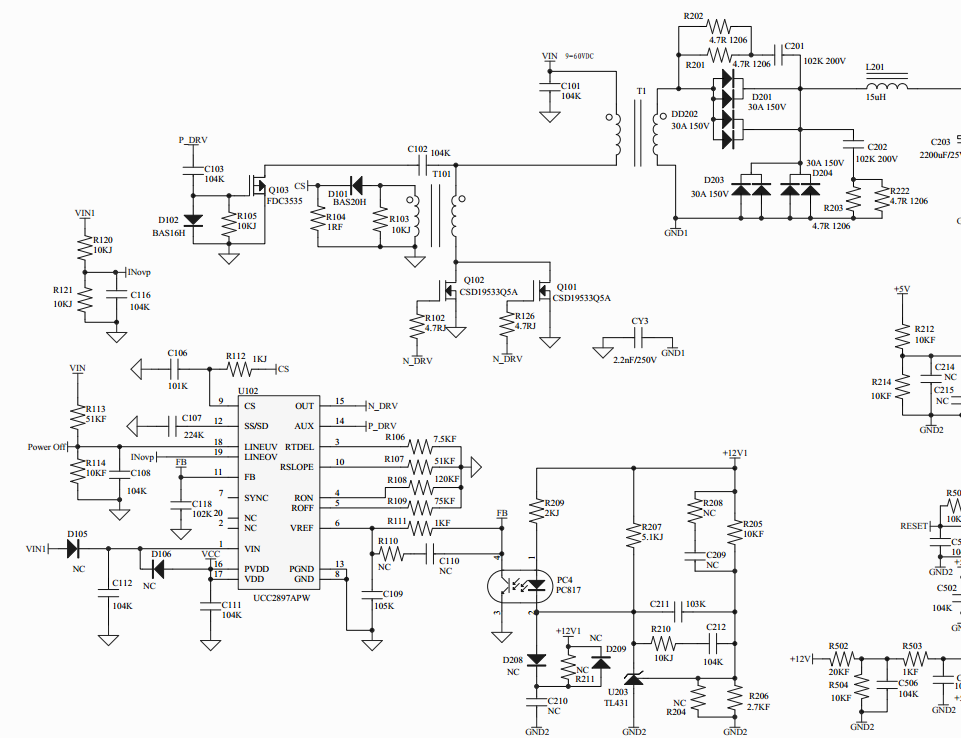
This thread has been locked.

If you have a related question, please click the "Ask a related question" button in the top right corner. The newly created question will be automatically linked to this question.

UCC2897A: 9-60V input, 12V/10A output = 120W, MosFET temperature is too high.

Part Number: UCC2897A

Hi Team

This curciut can work ,But still have 2 issue need your help.

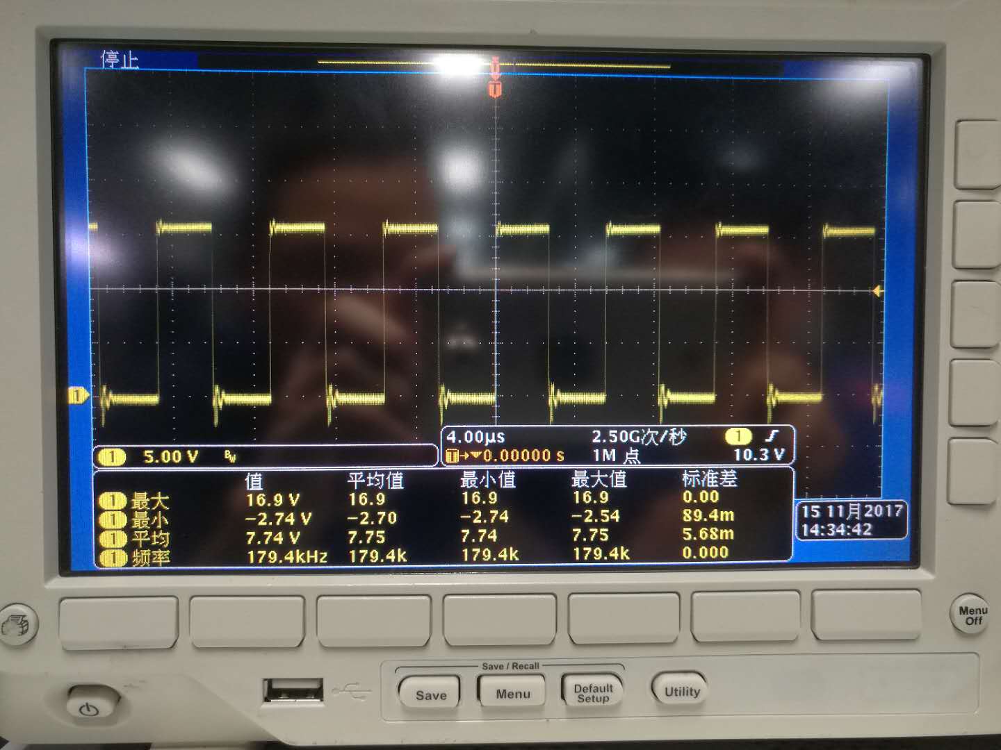
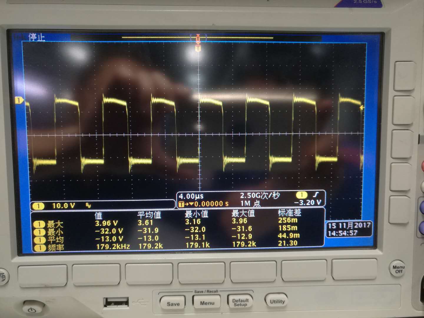
1. PMOS temperature is very high, when there is no load , PMOS temperatre can reach 140°.

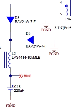
2. Could you give suggestion for BIAS inductance. Now we use 1mH。


  • Hello Wentao

    The UCC2897A EVM uses a 2uH output inductor with a 1:4 ratio between the main and aux windings so the aux winding will be about 32uH (Pulse Engineering type PA0373). 1mH will work but I'm not sure if it is optimum

    I'd suggest you do the following -

    Measure the DC load current taken from the Aux rail

    Select the bias inductor so that the peak to peak ripple current is 20% of the DC load current (20% is relatively arbitrary - you may want to have less ripple current which means a larger inductor or more ripple current with a smaller inductor but 20% is a good starting place)

    Calculate the inductance from L = Vbias*deltaT/deltaI where Vbias is the bias voltage you are generating, deltaT is the OFF time of the PWM at the minimum duty cycle (delta T is a maximum) and deltaI is the aforementioned 20% change in current.

    The output capacitance should be sized to reduce the ripple on the bias supply to an acceptable (low) level.

    Regards

    Colin

  • Hello Wentao
    I forgot to address your first question about the PMOS temperature.

    Check the maximum duty cycle clamp is set at the correct level to prevent over voltage conditions on the MOSFETs - although this is likely to be a problem for full loads rather than no-load

    It's difficult to see from the picture but it looks like the power train has lost ZVS at light loads and adjust the delay time accordingly using the resistor at the RDEL pin.

    Check that the gate drive voltage is still adequate to fully enhance the PMOS device.

    The documents at www.ti.com/.../getliterature.tsp
    and www.ti.com/.../slup112.pdf give lots of useful information about the ACF topology.

    Regards
    Colin
  •  Hi Colin

    This Time they has change schmatic and layout.

    And they have change protection style, when OCP,OVP or MCU request UCC2897A stop working and stop output, use optcoupler PC2 reply to Pull down UCC2897A's  LINEUV(18Pin) . Could you think it is ok, if it will give some influence when pull down this Pin.

    For more information, Please refer schmatic

  • Hi Wentao

    Pulling the LINEUV pin low is the recommended way to stop the controller.

    Regards
    Colin