This thread has been locked.

If you have a related question, please click the "Ask a related question" button in the top right corner. The newly created question will be automatically linked to this question.

UCC2803-Q1: SMPS without opto feedback

Part Number: UCC2803-Q1
Other Parts Discussed in Thread: UCC28730-Q1, UCC2803,

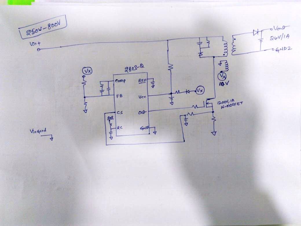
I am looking for the less BOM count design for 250Vin-800Vin DC supply, Where output is 24V/1A.

Can i remove the Opto section and auxiliary VCC section..

Vfeedback can i take from my output i.e 24V ??

  • Hi, Rami,

      I don't have all the information needed.

      Here are some assumptions I have based on your description.

      You are looking for a single 24V output, 1A design.

      If that is the case, you can simplify your design by removing all the things you don't need.

      To have the design without using opto, first you need to see if your 24V output has the common ground as the primary side controller.

      If yes, you can directly tie your 24V output to the feedback divider and close the loop.

      If no, you need to use an aux winding to create a voltage on the primary side, like the schematic in your attachment.

      You can also try UCC28730-Q1. It senses output voltage through the auxiliary winding and no opto coupler is needed.

      Let me know if this helps you to understand the options. Drop me a note if you have further questions.

  • i have no issue to create the aux winding.. can you please share the design schematic for me.. your assumptions are correct.
  • Hi, Rami,
    Is your output share the same ground as controller?
    Bing
  • Particularly I'm not looking for isolated supply.. If with common ground, BOM count reduces, i am ready to go for non isolated supply also..
    I am looking for very small footprint.. i.e as small as possible
  • Ok. Given you very wide input voltage and large voltage ratio between input and output, you'll need the transformer to help.

     See the attachment for the simplified schematic. You need to figure out the exactly values of the component. But the schematic gives you a starting point. You should add all the necessary functions, such as EMI filters, etc. to meet your final requirements.

    UCC2803Flybacknoniso.docx

  • Thanks sir..
    I will calculate..
    If i want isolated one one auxiliary supply is enough right?
    From auxiliary i will give the feedback. I am comfortable with 24 +/-1V on output..

    Even I am using external MOSFET in my application why input voltage is limited upto 800vdc only?
    I am planning to use this in my 660Vdc nominal lithium battery application.. Which is my electric vehicle bus application.. There maximum voltage 760V. Initially I planned to design with 1000Vdc input as my maximum value. From my charger i may get the pulse of 800vdc + while every 1st time connection..
  • Hi, Rami,

       This is correct. You might have to play with the aux winding rectifier a little bit to get the best performance.

      I suspect you don't want to have a resistor in series with the aux winding since that adds error to the sensed voltage. But it might smooth out the voltage ringing. You have to test to see which one is the case.

      Another trick you can play is to choose the appropriate rectification diode for the aux winding. If you can use slow diode like general purpose PN junction diode, the slow turn on could help to block the leakage spike and help on the voltage sensing. Same as previous point, you might want to play with the diode selection a little bit with different reverse recovery time and see which one gives you the best results.

      Final point is about the gate driver circuit. I simplified it as a single gate resistor. You might need to adjust that resistor or add diode and resistor in parallel so that you can adjust the turn on and turn off speed independently. We also put a resistor between MOSFET gate to source, at the range about 20kohm to 100kohm to help keep MOSFET off during the start up when IC is not powered up.

      Good luck and have fun with the circuit.

  • hi bing,

    thanks for your exp

    Even I am using external MOSFET in my application why input voltage is limited upto 800vdc only?
    I am planning to use this in my 660Vdc nominal lithium battery application.. Which is my electric vehicle bus application.. There maximum voltage 760V. Initially I planned to design with 1000Vdc input as my maximum value. From my charger i may get the pulse of 800vdc + while every 1st time connection..

  • Hi, Rami,
    I don't think your design will be limited to 800VDC. Given you have external MOSFET and transformer, you can adjust the voltage rating of your MOSFET and transformer turns ratio to meet your requirement.
    Let use know if this is what you are worry about. Or we can further help.
    Thanks.
    Bing
  • My Battery pack voltages as below

    Nominal voltage : 666V

    Minimum: 500V

    Maximum: 756V

    My Charger specification says that, at 800V there is a output over voltage protection.

    so request you to please suggest the DC-DC input limits..

  • Hi, Rami,

      Since your input voltage can go to 800V at over voltage protection condition, you need to consider the worst case and design your Flyback converter to handle the 800V input voltage.

      Let me know if this is clear.

      Thanks.

    Bing

  • Bing,

    you mean to say i can use UCC2803 RIGHT?

  • Hi, Rami,

      That is correct. You can use UCC2803-Q1

  • Is that schematic correct?

    Can i go for the PCB design..

  • Hi, Rami,

      Sorry for the late response. The schematic is correct.

      You might need to adjust component values but the schematic as it is should be fine.

      Let us know if you have any further questions.

      Thanks.