This thread has been locked.

If you have a related question, please click the "Ask a related question" button in the top right corner. The newly created question will be automatically linked to this question.

TPS92692-Q1: There has the Led lights flashing when remove the P-Channel Mosfet ( QDIM)

Part Number: TPS92692-Q1

Input:DC 6-16V  Output:LED*12S/0.3A

F(PWN Dimming)=200hz

Issue:The Led lights flashing occurrence when remove  the dimming FET and PWM duty cycle is about 8% .The PDRV pin is floating and the function of spread Spectrum Frequency Modulation isn’t used in the design. Could you help check if the dimming FET can removed or not when the  PWM duty cycle  is very low
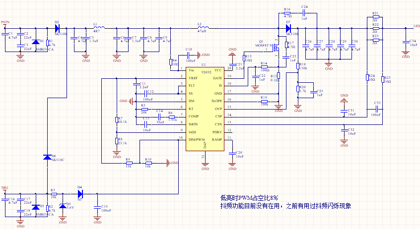
SCH is as below:

  • Hello Hope,

    The point of the disconnect FET is to keep the output voltage at a certain level when PWM is low. COMP also disconnects so that when you pull PWM high the output capacitors and COMP are both close to where they need to be for a fast response. Without the FET the output caps can discharge much more so the transient as COMP tries to adjust could cause over/undershoots and could vary cycle to cycle.

    You can still dim that way but you will likely need to adjust the COMP values to prevent any sort of oscillation between Vout and COMP changing. The FET will improve dimming quite a bit however.

    Regards,

    Clint

  • dear Clint,
    your mean is we can change the COMP values to slove the issue,right? I neede enlarge the COMP values or change the comp‘topology
    Thanks a lot
  • Dear Clint,
    We try to adjust the COMP values ,but we cann't solve the issue. Could you give some more advices to debug. if you have some success case about the issue,please share it to us for refer
    Thanks a lot
  • Hello Hope,

    It will always work best with the FET, but I've seen it work without. You usually need a good amount of output capacitance (you may have enough) and to really dampen the response. You usually need to use something like a 0.1uF or 1uF capacitor from COMP directly to ground.

    Regards,

    Clint

  • Dear Sir
    We had adjust the COMP values, but the issue hadn’t been solved. We try to connect a 510kΩ resistor to GND , the led flashing issue has disappeared and the GATE drive waveform is normal. But as the description in the datasheet, if we connect a 249-kΩ resistor to GND , the PWM generator have been disabled. So could you help explain the question and check whether there have some risk if we change C20 from 10nf to 510K in the design or not.
  • Hello Hope,

    That is really only for analog to PWM dimming if that is needed. It doesn't look like you are doing analog to PWM dimming, so that is perfectly fine to connect a resistor to ground to disable it, in fact it is preferable for any case when you are not using analog to PWM dimming.

    Regards,

    Clint

  • Hi Clinton,

    Thanks for your reply, connecting resistor between RAMP to ground is not the point, the point is why after we disabled the RAMP function, it still can achieve dimming function?

    thanks.

  • Hello Leo,

    I understand. The PWM/DIM pin is dual function, but only one function should be used in an application. If you drive it with a PWM signal the internal ramp should be disabled, otherwise when it is transitioning up/down the internal PWM can override at certain times depending on the speed of the edges, and that is likely the cause of your extra switching. So if you want to drive that pin with a square wave for PWM dimming you want to disable the analog-to-PWM dimming functions to avoid issues. I hope that helps.

    Regards,

    Clint

  • Hi Client,

    Thanks. actually, we use dc voltage 1.16V as the DIM input instead of external PWM signal, you could refer to the schematic above. however, the dimming function still performed after RAMP disabled, that's what confuses us quite a bit.

  • Hello Leo,

    Ok, I misunderstood. That is kind of odd. So that leaves me with two questions:

    1. Did you have the RAMP capacitor populated the first time around with no resistor as shown in the schematic? If so did you try a larger value cap like 100nF to see if it makes a difference? I only ask because with DIM at 1.16V you are very close to the 1V threshold. Given that you are close and there will be some tolerances I could see any slight bouncing on RAMP causing flickering in this case.

    2. Did you verify that RAMP is actually disabled with a 510k resistor? I'm guessing the 249k was specified to ensure the RAMP pin is pulled below a certain value. I could see the possibility that with a higher value it could still reach a high enough voltage to trigger perhaps.

    Otherwise with such odd behavior we may want to consider layout as a possible culprit.

    Regards,

    Clint

  • Hi Clint,

    We will confirm this and give feedback. by the way, could you show the typical layout issue which would cause this kind of misbehavior? We'd like to review the layout carefully as well.

    thanks a lot.

  • Hello Leo,

    First of all good grounding is essential and the basis of a good layout. A ground plane is recommended with all power component ground tied directly to it with vias. You also want the main power grounds (IC, RIS, Cout) close together.

    Other common mistakes are a long gate trace, long CS traces that are run beneath power components and/or the inductor and also not kelvin connected, and/or a long IS trace.

    Generally it is a good idea to look at the EVM layout and follow that closely. It's a proven layout that has been heavily tested.

    Regards,

    Clint

  • Hi Clint,

    Thanks for your suggestion, we will double check this.