


Hello!
We have custom PCB with BQ25895 charger IC, the schematic of the charger part is shown below:
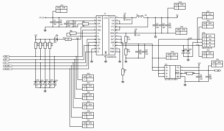
VBUS input is supplied from standard PC USB 2.0 port. Battery type is Li-Ion battery with uknown capacity (prbably 2000-4000 Ah). Vsys voltage supplies GSM/GPS/BLE module SIM868E and Cortex-M0 microcontroller STM32F072 and a bunch of peripherals such as accelerometer, flash memory, LEDs, etc.. MCU is supplied using LDO converter that provides 3.0 V. To exclude Vsys overload we disconnected SIM868E from Vsys. CE pin is connected to the host and is pulled LOW.
Here's I2C registers dump that was read when only external source was supplied:
Reg 0: 00111111b
Reg 1: 00000101b
Reg 2: 11100000b
Reg 3: 10010010b
Reg 4: 00100000b
Reg 5: 00010011b
Reg 6: 01011110b
Reg 7: 10001101b
Reg 8: 00000011b
Reg 9: 01000100b
Reg a: 10010011b
Reg b: 00100111b
Reg c: 10000001b
Reg d: 00010100b
Reg e: 00000000b
Reg f: 00000000b
Reg 10: 01111111b
Reg 11: 10011001b
Reg 12: 00000000b
Reg 13: 00111111b
Reg 14: 00111001b
We have to major problems with the charger IC:
1) When both external and battery are plugged in the system voltage is unstable and thus we cannot pull the registers dump. Below are several screenshots taken from oscilloscope:
DSEL: https://www.dropbox.com/s/dmv4cfcd88pzs9o/dsel.jpg?dl=0
VSYS: https://www.dropbox.com/s/azryl6mnbls9mix/vsys.jpg?dl=0
INT: https://www.dropbox.com/s/o2l006wzalfsqtu/int.jpg?dl=0
When only one source is plugged is the host works
2) The battery is not being charged although we have looked through IC datasheet several times and it seems that all parameters are OK and the charging should work. STAT LED is turned off which means that charging is disable but we don't know what is wrong with schematic/registers value. We tried to short D+/D- pins as well as connect them to the corresponding USB lines. Actual value of ILIM resistor (R59) is 120 Ohms.
Can anyone help us with the issues? We are struggling with the several days and still no success.
