This thread has been locked.

If you have a related question, please click the "Ask a related question" button in the top right corner. The newly created question will be automatically linked to this question.

TPS62172: high quiescent current draw

Part Number: TPS62172


My customer is using the TPS62172 and seems to be measuring high quiescent current when the input voltage is at 3.7V.  Part is used to step down to 3.3V with an input voltage range up to 6V.  When input voltage is about 3.7V the customer is measuring about 3mA of idle current (even with load disconnected.).  I can share the schematic directly at your request.

They were able to take some scope shots as well.  At 3.8V in (load is disconnected) they measure ~20uA idle current and the switch node looks like this:

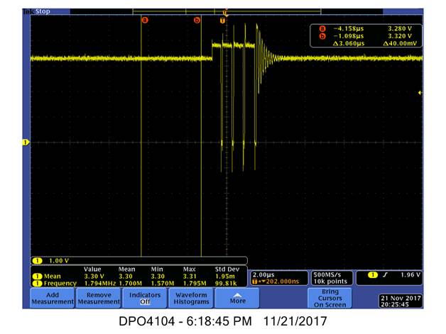
When the input voltage is decreased to 3.7V they see idle current rise to about 3mA and the switch node looks like this:

Which looks like normal full PWM mode.  This is with the load disconnected.

Is this typical operation?  The inductor used is a 3.3uH (NR3015T3R3)

Thanks,

Dan

  • Hi Dan,

    I feel like I answered this question before in another thread/email, but in any case the D/S explains on page 10 and this app note explains why this is not Iq: www.ti.com/.../slyt412.pdf

    Can you share some more application details (EE, Vin type, Vin range, load range (min and max), etc.) via email so we can come to the best solution?
  • Thanks, Chris - that app note is awesome.

    I'm more concerned because it seems like the part is going from PFM to PWM mode - but I think I figured it out: the datasheet states specifically: "When VIN decreases to typically 15% above VOUT, the TPS6217x does not enter power save mode, regardless of
    the load current. The device maintains output regulation in PWM mode."
    Doing a quick calculation on a 3.3V out... gives about 3.795V for Vin - so anything lower than that would cause the output to remain in PWM.
    Shoot. This could be a problem for them, since fixed PWM has much higher average current. I'll send over their current schematic and details via email and see if we can find a solution.

    Thanks,
    Dan