Hello
I have to analyze a almost finished system with a small handheld device and its related docking station. Both coils Tx (17 windings, ca. 20mm diameter) and Rx (15 windings, ca. 15mm diameter) are customized. Based on below measured inductance values, the coupling factor is 0.72
LRx,stray = 11.8 µH (with LCR-Meter @ 10kHz)
LRx (=L’S) = 25.3 µH (with LCR-Meter @ 10kHz)
LS = 19.62 µH (with LCR-Meter @ 10kHz)
LTx,stray = 8.114 µH (with VNA @ 100 kHz)
LTx = 17.363 µH (with VNA @ 100 kHz)
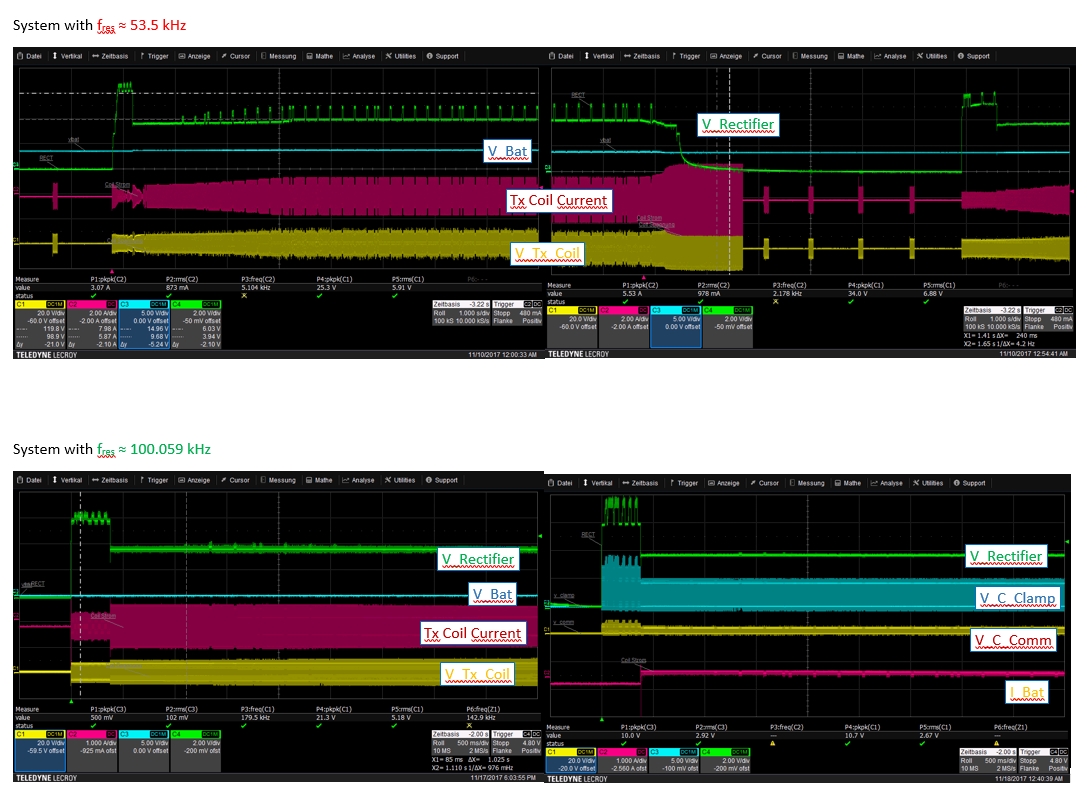
The transmitters resonant frequency is 100 kHz (S11 measurement with VNA). The original assembly of the handheld device (C = 350 nF, L 25.3 uH) results in a resonant frequency of ca. 55 kHz. I corrected the value to 100 kHz by setting the Cs to 100 nF by using the formulas of the datasheet
With the original assembly, the communication peaks on Vrect are visible while in the corrected version, those peaks are only visible if the battery output is not active. Increasing the comm caps does not help.
My questions are:
1) Don’t have I to take the mutual inductance only for calculating the series-resonant capacitor Cs?
2) Why does’nt the communication work anymore after putting the receiver resonant frequency to 100 kHz?
3) Why do I get a positive voltage increase on V_Rectifier while communication is active?
Thanks to anyone for helping me