This thread has been locked.

If you have a related question, please click the "Ask a related question" button in the top right corner. The newly created question will be automatically linked to this question.

TPS56221: ILIM not working, looks like PWM signal

Part Number: TPS56221


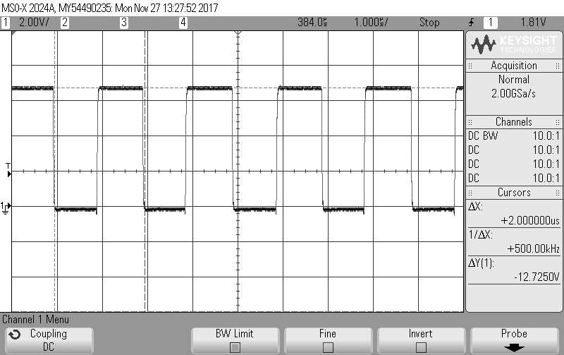
I've set up my TPS56221 like the example in the datasheet and everything is working great except it doesn't seem like the OCP functionality is working. I've used a 1.75kOhm resistor which should correlate to a 19A current limit. However the device only enters hiccup mode when the current goes past the maximum value (25A). I've probed the ILIM pin and it looks like a PWM signal of 500 kHz (the current switching frequency) with a high value of 6.5V (the BP regulator?). I thought it should be a current source of 10 uA ? Is this what the signal is supped to look like? Any idea why OCP is not working as it should ?

Thanks in advance!

  • Can you post your input voltage, output voltage, schematic and PCB layout?
  • Input Voltage = 12V

    Output Voltage = 5.5V

    I'm not at liberty to share the entire schematic/layout - it is nearly identical to the datasheet example

    Below is the layout section with the Ilim resistor - less than 2mm away from the chip.

  • I need more details to calculate your OCP settingbut it looks like something is not working properly. The voltage on the ILIM pin should be between 6 mV and 50 mV. If it reaches above 300 mV during calibration, the current limit is disabled. How many samples out of how many total are showing this behavior? If it is only one I would check carefully for solder defects, wrong components, etc. It may also be possible you have damaged the IC. Let us know what you find.