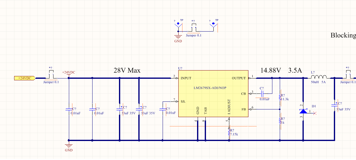
I purchased the LM2673SX-ADJ/NOPB part and followed the design in the LM2673 Doc# SNV50300 April 2000 , Revised 2016.. I copied the design from section 8.2.3.2.
Attached is the schematic we copied from that section.
Test Results:
With a 24 volt supply with 3.5 amp capacity I checked and double checked the connections and ohm checked everything. It was built on a bread board system. I powered it up and got 14.33 Volts on the output. I expected 14.88, but I assumed my resistors were not perfect and it was a wired prototyped. I jumped for joy! Then I wanted to load it down to confirm it was regulating. I had some 50 W resistor and made a 12 ohm load.
Quick current calculation 14.33 v / 12 ohm = 1.19 Amp Quick power calculation P = ISqu x R P=1.42 A x 12 ohm = 17 W
Once the load was attached the voltage on the regulator dropped to 9.73V. It was steady. The device was not working properly. I checked that the 24 V was not causing the problem and saw it dropped from 24.21 v to 24.13 v, no problem with the supply.
Troubleshooting with other we tested the following.
> Could the current limiting resistor on pin 5 be too large for the 1.2A load? What is the value of this resistor?
Ans: 7.15K
> Could you compare the Cboostrap (pin3) voltage with no-load and loaded?
Ans: Vin, so you have a base line is 24.20 V
Ans: Pin 3 no load voltage is 23.81 V
Ans: Pin 3 with load voltage is 19.33 V
> Compare Feedback (FB pin6) voltage with no-load and loaded
Ans: Pin 6 no load voltage is 1.207 V
Ans: Pin 6 with load voltage is .947
Other testing resulted with the following voltages when we change the resistor on I Adjust.
Change value from 7 k to 2.946 K , loaded the voltage went to 21.6V .
Change value from 7 k to 3.2 K , loaded the voltage went to 10.00V .
Change value from 7 k to 4.9K , loaded the voltage went to 9.97 V.
Change value from 7 k to 6K , loaded the voltage went to 10.02 V.
Can you suggest any ideas as to why we do not have proper regulation?
Thank you
Rob


