This thread has been locked.

If you have a related question, please click the "Ask a related question" button in the top right corner. The newly created question will be automatically linked to this question.

TL494: Low Temperature Characteristics of TL494

Part Number: TL494


Dear, All

Customers are considering replacing uPC494 with TL474.
As a result of the experiment, it was found that there is a difference in characteristics at low temperature.
But I do not know the reason.
Please tell me the possible causes.

Operating conditions:
Vin: 17V to 29V
Vout: 2V
Iout: 200mA Max

Condition on occurrence of phenomenon:
Ta = -10 degrees C
Vin = 19.2V
Iout = 165mA

When TL494 is used, it drops to 1.924V in one device and it drops to 1.890V in other devices.
When uPC494 is used, about 2V output is maintained.
Even when TL494 is used, when Vin is 24V, the output voltage is about 2V.
Even when Vin is 19.2V, the output voltage is about 2V when the load current is 50mA.
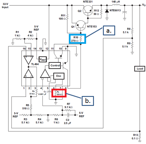
The circuit configuration is as follows, but the constants of the resistance etc. used are changed.


In the customer's circuit, the following resistance values are used for the figures a. And b.
a. = 2.2 kOhm
b. = 5.6 kOhm

It was found that by changing the resistance value as follows, it is possible to make the characteristics the same as those of uPC494.
a. : 2.2 kOhm --> 910 Ohm
b. : 5.6 kOhm --> 1.6 kOhm
Only one change alone did not result in the same characteristics.
Both of them have the same characteristics as uPC494 only after changing the resistance value.
There is no particular difference in the prescribed value of the data sheet, and there is only a slight difference in the typical value of the output voltage, so the reason is not known.
Customers say they can not change without knowing the reason.
Please tell me the reason for being estimated.

Thanks, Masami M.

  • Thanks for your interest in TI here. I've contacted the appropriate product group. You should hear from them soon.

  • Hi, Qu-san,

    Thank you for your support.
    I will wait for the reply.

    Thanks, Masami M.

  • Hi, Qu-san,

    Thank you for your support.
    Have you got information from the appropriate product group?

    Thanks, Masami M.

  • Hello Masami-san

    I'm afraid that I can't offer any clear reason for the different behaviour of the two devices. As you noted the two devices are essentially identical.

    Reducing the value of the base resistor (R10 above) will increase the amount of current that the controller can supply to the base of the switching transistor and changing the RT resistor from 5.6 kOhm --> 1.6 kOhm would increase the switching frequency significantly. Can you confirm that the frequency was increased by this change and if so what was the original and new switching frequencies.
    I don't have access to the customer's board nor do I have NEC devices available to me but if I wanted to know what was causing this behaviour I would do the following
    1/ Look carefully at the decoupling capacitors between VCC and GND
    2/ Look carefully at the REF output from both controllers
    3/ Does the NEC device show the same behaviour at a lower input voltage - 16V or 15V or lower

    Please send commercial details to me at colingillmor@ti.com -- This will help us decide on our next steps.

    Regards
    Colin
  • Hi, colin-san,

    Thank you for your support.
    Please have the customer observe them on their board so please wait for a while.
    I will inform you of the result by email.

    Thanks, Masami M.