This thread has been locked.

If you have a related question, please click the "Ask a related question" button in the top right corner. The newly created question will be automatically linked to this question.

LP5907: Noise Measurement

Part Number: LP5907
Other Parts Discussed in Thread: OPA188

Hi team,

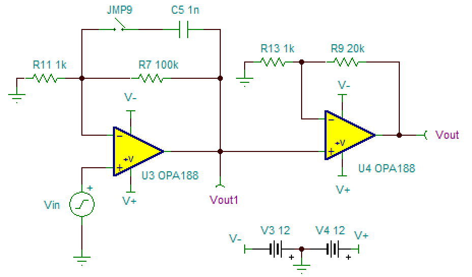
LP5907 is an ultra-low-noise LDO. Its output voltage noise is less than 6.5 µVRMS. How can I measure it in lab? The oscilloscope in the lab cannot measure voltage less than 1mV, is there any other way to measure it? Or do I have to use a more accurate instrument to measure? Thank you!

Best Regards

Hao

  • Hello Hao,

    See the guide : How to measure LDO noise ...

  • Hi Hao,

    Please also see this video.
    training.ti.com/engineer-it-how-measure-ldo-noise-and-psrr

    Regards,
    Jason Song
  • For what it might be worth, my own set-up for rms noise included:

    1) High capacity battery power supply to ensure low (no) Vin noise.
    2) Shielding from environmental magnetic electro-static fields from lighting or other nearby equipment (i.e. a metal box)
    3) A 60dB wide bandwidth AC amplifier, a version of the Jim Williams amplifier circuit shown in Figure 2 in LTC Application Note 83
    cds.linear.com/.../an83f.pdf
    4) A LeCroy oscilloscope to set the sample rate, averaging, LSB, max bandwidth, and calculate the rms value.
    A spectrum analyzer can be used in place of the oscilloscope.
  • Dear all,

    Thank you! All your answers are valuable for me. I read them all, but there is no any AC amplifier, so I used the signal analyzer to test the noise of amplifier OPA188, the schematic is as follows:

    The non-inverting is grounded in measurement, the first picture in the following shows the noise floor is -110dBm, and the second picture shows the noise of the circuit is about -80dBm over frequency higher than 15kHz. -80dBm means the noise voltage is 22uV, the simulated output noise of the circuit is 3.59mV, why the measured noise is far less than the simulated? I connected the output to the signal analyzer with a BNC.

    There are another two questions, could you please help explain? Thank you!

    1. Why the noise line in second picture goes down to -98dBm and then goes up slowly to -80dBm? It doesn’t make any sense.
    2. The RF input of signal analyzer says the maximum continuous power is +30dBm (1 W), if I want to measure the output noise of LP5907 (3.3V output voltage) with 100Ω load, is it safe to connect the output pin to RF input directly? The input impendence is 50Ω, so the maximum input voltage is 7V, so I think it’s safe, am I right?