This thread has been locked.

If you have a related question, please click the "Ask a related question" button in the top right corner. The newly created question will be automatically linked to this question.

BQ78PL114 + BQ76PL102 fail randomly

Other Parts Discussed in Thread: BQ78PL114, BQWIZARD, BQ76PL102

We are currently assembly a few hundred of system with BQ78PL114 + BQ76PL10. We have 5 cells in serie (typical voltage at assembly of 3.2V), so we have one slave and one master. All of our batteries have FW4452 (we designed when FW5000 was not released, so we cannot upgrade with our current PCBs)

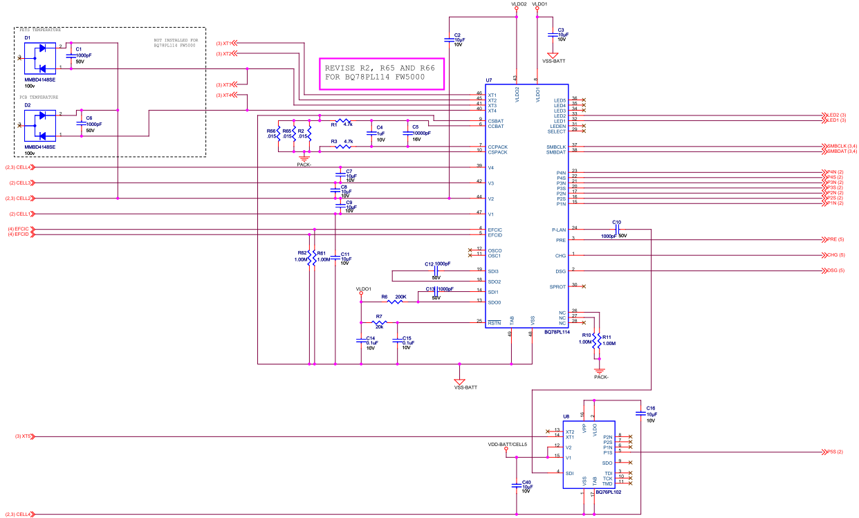
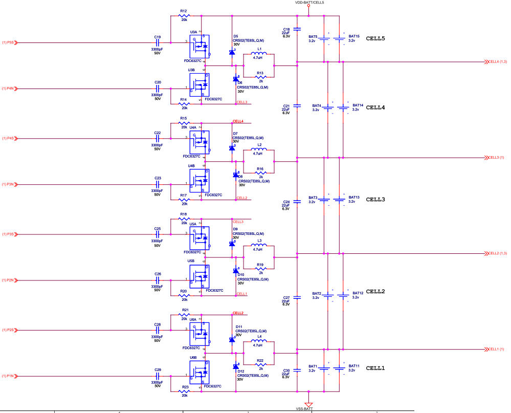
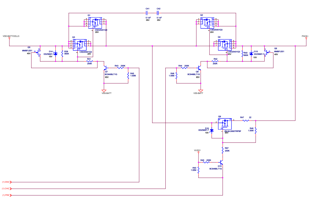
You will find at the end of this post picture of the schematics we have. They are very similar to the reference specs

The issue we're having is that after assembly, many (>25%) of the boards fails to operate correctly. The typical problem is that the slave is unresponsive. I can communicate with BQWizard but I get some garbages values (I can read and write in some fields such as "manufacturer", and it reads back correctly) but when it comes to reading voltages or temperature, all I get is the default 2000mv.

I've been able to somehow revive it by loading a 4 cells .aux files so that it ignores the 5th cell, and it works (all voltage and temperature can be read, except for the 5th cell)

The VLAN flag doesn't raise, but I can assume that the slave is broken and that it prevents the master from functionning correctly.

Moreover, on broken boards, the VLDO and VPP pin of the slave read 3.2v instead of 2.5V (3.2v being the voltage of the cell). It's like if the LDO blew up and outputs the cell voltage without regulating.

I've seen this also on some LDO on the master (VLDO1 and VLDO2). In that case, communication was not possible at all

I am taking extreme care of loading the cells in order, beginning with the lowest cell, then going up until the most positive cell is connected. But that doesn't seem to solve the problem.

I am also taking extreme care in regards to ESD. The circuit also have most ESD protections of the EVM.

Somehow these problems occurs out of the box, sometimes they just stop working after assembly for no reason while they were working fine before.

The chips seem very weakened; they were assembled by a professionnal assembly fab. I am starting to question the reflow soldering temperature, but since I cannot find any information in the datasheets


Did anyone experience such mysterious fails ? Anyone can explain why such high voltage is present on the LDO pin ?


  • Hi Mathieu,

    we are experiencing very similar problems. Sometimes the boards even work for a time but then we get VLAN error. Did you found a reason in the mean time?

    Best regards,

    Dirk

  • Hi Dirk,

    I spoke with TI over the phone on this issue. They've confirmed it happens, but they couldn't pinpoint to a solution. Their advice was to make sure you apply power in this order :

    VSS, 2nd cell, 1st cell, 4th cell, 3rd cell, etc

    This is the sequence we're applying, and so far it's good, but we didn't start a volume production with this configuration yet. Time will tell

  • Hi Mathieu,

    to switch on the cells in the right order is a common advice von TI, but its not really a sign of a good chipdesign. The chip should not be malfunction just because a short power down due to a weak contact occured.

    Anyway we have found out recently that there is an other issue which effects VLAN strongly. We observed random loose of VLAN communication after some weeks in the field. We are quite sure that the chip was not disconnected during this period, so the poweron sequence should be no explanation. We thought about possible reasons for this behaviour and we came up with the idea, that the SDI entrance was probably stressed during power on sequence, i.e. bevore the capacitor is charged the voltage level at the SDI entrance is is some volt below the corresponding vss of the bq76pl102. To avoid this we have integrated schottky diodes in our design as usual for esd protection. As a result no VLAN communication at all was possible. The reason for this behaviour was junction capacitance of the diodes which was in the range of 100 pF. In one case even the backward resistance of the diode was small enough to pull down the entrance. In other words the SDI entrance is very sensitiv to capacitive coupling and high ohmic loads which both may occur from board design or air humidity.

    Question to TI: Is there any workaround to make the communication more rubust, e.g. with a larger coupling capacity and a pull-up resistor to VLDO?

    Best regards

    Dirk

  • It is my opinion as well that the chip should not malfunction on any powerdown.

    I've had the same problem as yours; my chips also fail randomly in the field. I couldn't explain this besides that maybe the chip was damaged at assembly but not enough so that it would fail in our hands.

    TI couldn't give any more explanation, they couldn't help more.