This thread has been locked.

If you have a related question, please click the "Ask a related question" button in the top right corner. The newly created question will be automatically linked to this question.

LM3481-FLYBACKEVM: Unstable Flyback-Converter

Part Number: LM3481-FLYBACKEVM
Other Parts Discussed in Thread: LM3481,

Hello,

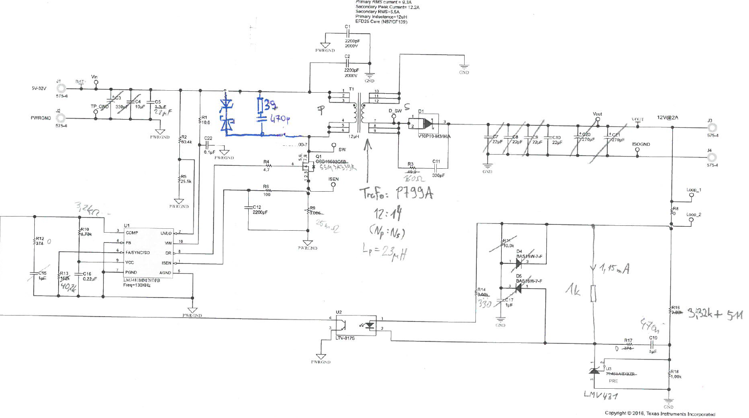
I would like to design a Flyback-Converter using the LM3481.
I use the LM3481-FLYBACKEVM to test my design.

The specification is as follows:

Vin = 5.4 to 17 V
Vout = 6 V +/- 1%
Iout = 400 mA
switching frequency: 500 kHz

Failure Mode:

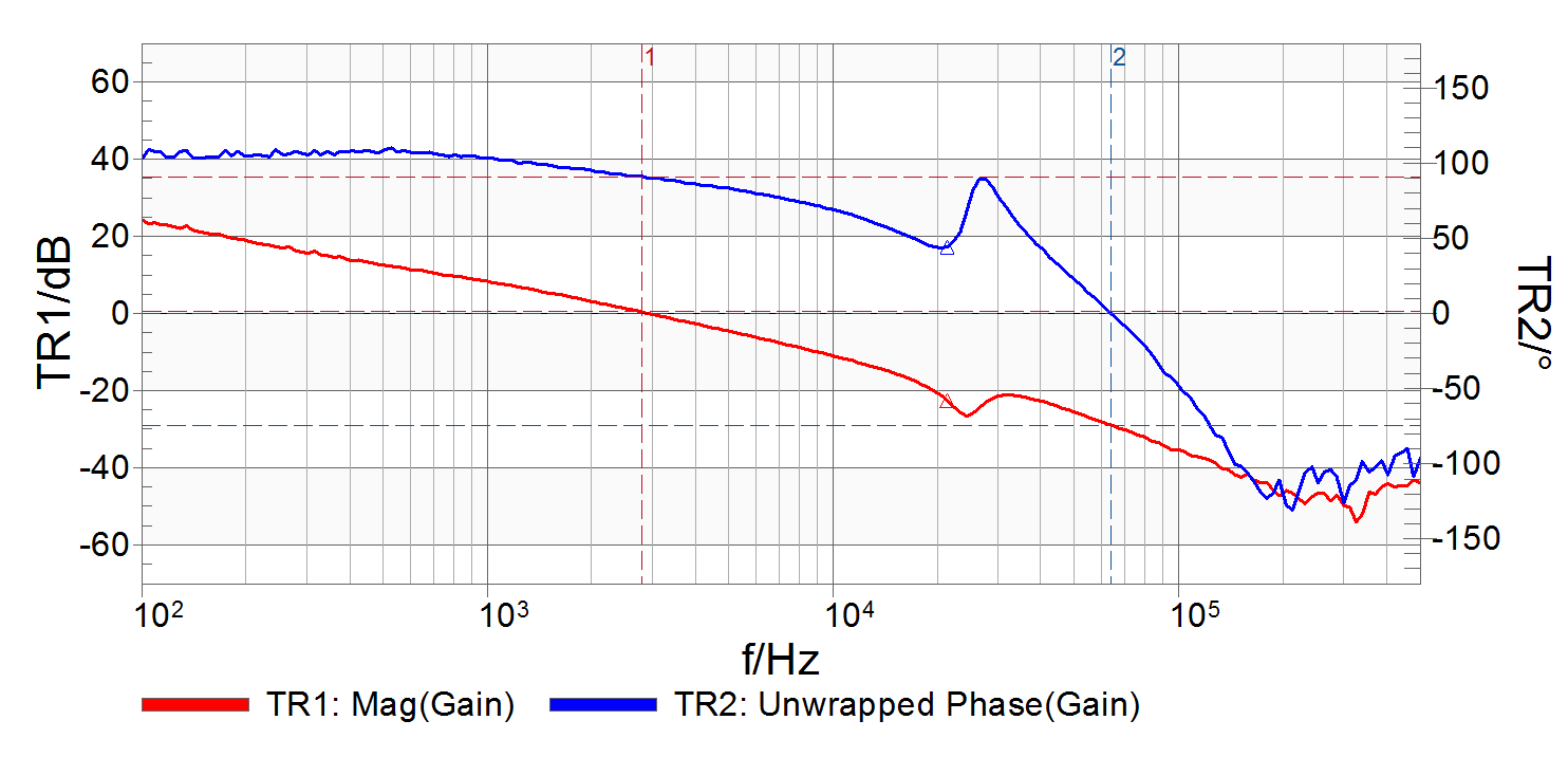
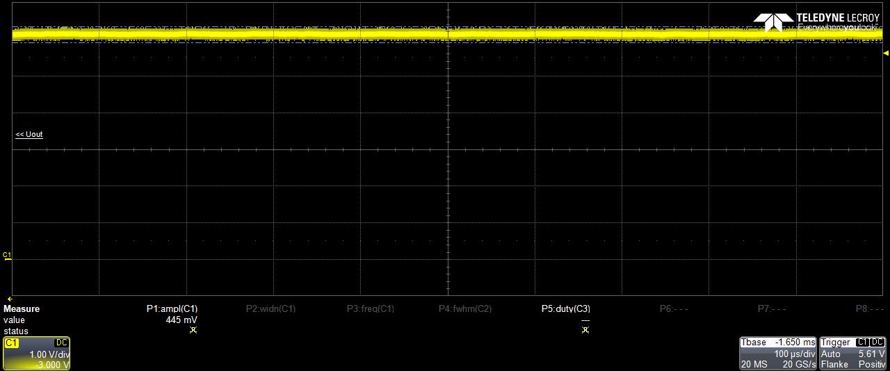
The Powersupply shows unstable behaviour, espescially with an output load.
The Vce of the optocoupler oscillates and Vgs consists of Bursts. A description
with screenshots from measurements is attached to the post.

Schematic:

FailureMode_Flyback.pdf


Thank you for your Support.

Regards

Adam 

  • Hi Adam,

    To correctly compensate the design please follow the guide lines set out in this application note. Please also try adding more output capacitance. It appears that much of it has been removed from the EVM,

    Thanks,

    Garrett

  • Hi Garrett,

    thank you for your tips. I increased the Output capacitance of the converter to 66µF. I also calculated the values for the compensation network according
    to the application note. Now I can measure the following bode plot with a load of 100 mA. Phase margin is 90° and gain margin is 30 dB.
    However, at a load current of 150 mA the Flyback still begins to oscillate.

    Regards

    Adam

  • HI Adam,

    I would suggest lowing the cross over frequency. In a converter that has a RHP zero in the control loop it is normal to set the cross over frequnecy around 1/4 of the RHP zero frequency.

    Can you please post a waveform showing VOUT, SW node and the COMP voltage?

    Thanks,

    Garrett

  • Hello Garrett,

    I measured the voltages at VOUT, SW node and the COMP pin. The waveforms corespond to the
    last bode plot I posted with a cross over frequency of 2.8kHz, Phase margin 90°, gain margin 30 dB at a load
    of 100 mA and Vin = 5.4V. It carried out that the flyback don't oscillate at 100 mA load when the load is switched on
    when the output voltage is already at its nominal value of 6V.


    CH1: Vout (2V/Div) (yellow), CH2: Vin (2V/Div) (magenta), CH3: Vgs (2V/Div) (cyan), CH4: Vfb (2V/Div) (green)


    CH1: Vds (10V/Div) (yellow), CH3: Vgs (2V/Div) (cyan), CH4: Vfb (1V/Div) (green)


    CH1: Vds (10V/Div) (yellow), CH3: Vgs (2V/Div) (cyan), CH4: Vfb (1V/Div) (green)

    Now I lowered the cross over frequency down to 1 kHz. To achieve that frequency, I changed the values of the following components:

    R12 = R17 = 162 -> 1k15
    C15 = C19 = 3u -> 680n
    R10 = 2k49 (no change)
    R14 = 1k87 (no change)

    The Flyback begins to oscillate, even with no load. A bode plot could not be measured because of to much noise.

    Regards

    Adam

  • Here a Plot of the Output voltage:

  • Here a plot with 100µs/ Div.

  • Hi Adam,

    I am surprised that the duty cycle is so high based on the turns ratio of the transformer. The maximum duty cycle should be around 50% (VIN~5.4V) but based on the waveforms it looks much larger. Are the transformer parameters correct that were provided in the first post?

    What is the voltage that the switching node is being clamped at? Please make sure that the voltage reference is being supplied with enough current.

    Thanks,

    Garrett