This thread has been locked.

If you have a related question, please click the "Ask a related question" button in the top right corner. The newly created question will be automatically linked to this question.

UCC28711: Tida-00173 tecnical help

Part Number: UCC28711
Other Parts Discussed in Thread: TIDA-00173

Hi,

I was previously posting in another forum and a TI staff member by the name of Ulrich Goerke was replying to me but I am not getting any replies there anymore.

I have designed a power supply circuit as detailed in tida-00173 and I am not getting the required output. 

I am using the same component values as mentioned in the TIDA except NTC pin which I have left open.

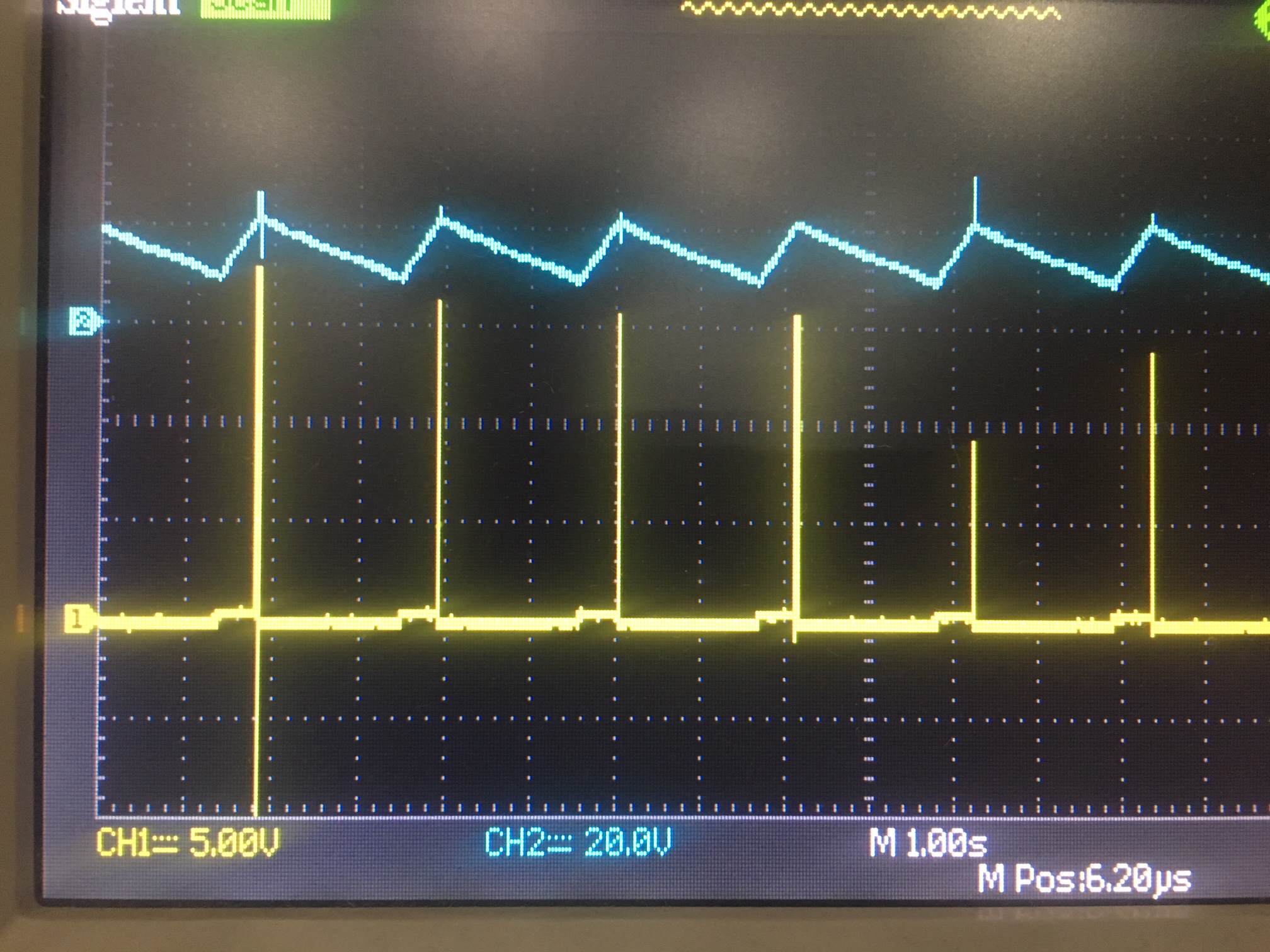
When I apply the input voltage (400V), I get the following waveforms (the blue one is the VDD pin and the yellow one is the NTC pin) :-

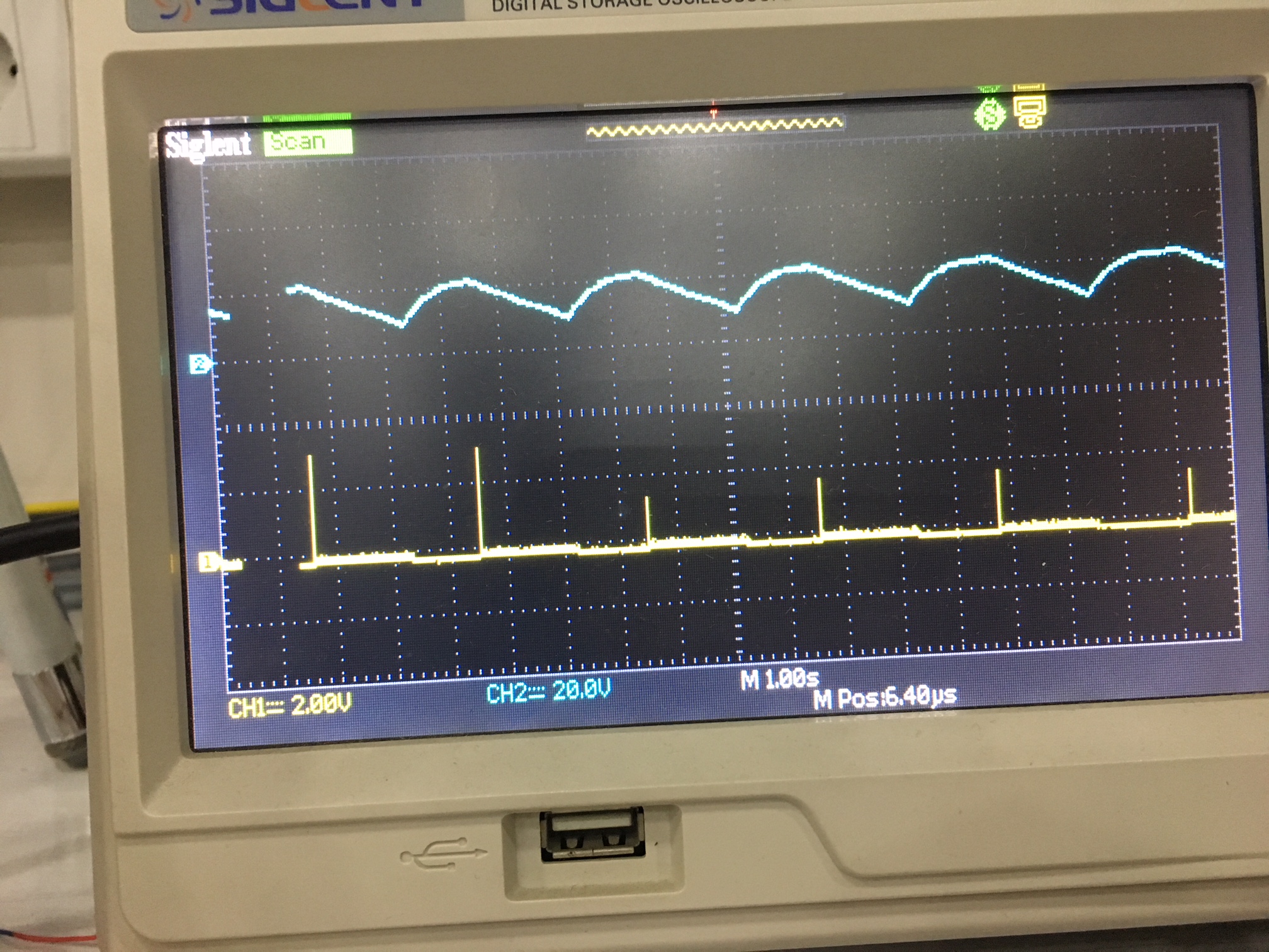
I do realise that the NTC pin should show a solid 5V after startup and should not show spikes but this what I am getting even after changing multiple ICs. 

The output voltage shows random variations between 9V-18V which is incorrect. Can Mr. Ulrich kindly help me out?

  • Refer to the post above, I changed the IC and the NTC pin now shows 5V on startup and I believe that there is no issue with the NTC pin.

    But still the IC doesn't start switching. Here is the waveform of the latest behavior. The blue channel shows VDD and the yellow channel now shows the gate drive pulses.

    1) The gate drive pin shows a single pulse after which the IC goes into shutdown. The startup sequence of three gate drive pulses does not occur. What does this tell about the type of fault that is occurring? My guess is that it has something to do with the voltage at CS pin. Otherwise it would have shown three pulses and then gone into shutdown. 

    2) The input voltage applied on HV pin is 425V.

    3) I have also tried lowering the values of R27 and R26 to 80K and 27K respectively (they were previously 91k and 30K), but there is no change in the result. 

    4) I have tried changing the values of Rs resistor from 0.91 Ohm as given in the TIDA to 1 ohm, 2.2 Ohm and 4.7 Ohm, but no change in the result.  

    5) Should I try connecting the resistor to the NTC pin or should I leave it open?


  • Ashan,

    Apologies for the delay with this response.

    What are your specifications for input voltage, output voltage(s), power, etc.?

    Are you targeting 24 V out same as TIDA-00173?

    When you power up, what is the output load? Is it open circuit/no-load? You seem to be getting some output voltage 9..18 V, or are you referring to VDD?


    Clearly, the IC is trying to switch when VDD charges up to the start threshold of ~21 V, but it is detecting a fault, and this causes PWM to stop, the IC goes to low power mode, VDD discharges to the UV level and then the cycle repeats.

    That is why SD internally pulls up for only a short time.


    You should be ok to leave the NTC pin open, that is not the cause of the issue.


    Can you zoom in and check the on-time of the single gate pulse? If this is quite long (several us), then it indicates a CS fault – either the CS pin is shorted, or the series resistor is open or too high impedance. Or there is a genuine over-current event due to a short in the system, or a reverse winding polarity in the transformer.

    I would suggest checking the signals on DRV & CS @ 1 us/div to help debug.

    There is also a very useful troubleshooting guide here that might help:
    www.ti.com/.../slua783.pdf

    Thanks,
    Bernard