This thread has been locked.

If you have a related question, please click the "Ask a related question" button in the top right corner. The newly created question will be automatically linked to this question.

TPS63031 - Possible excessive current consumption

Other Parts Discussed in Thread: TPS63031, TPS63030

Hi,

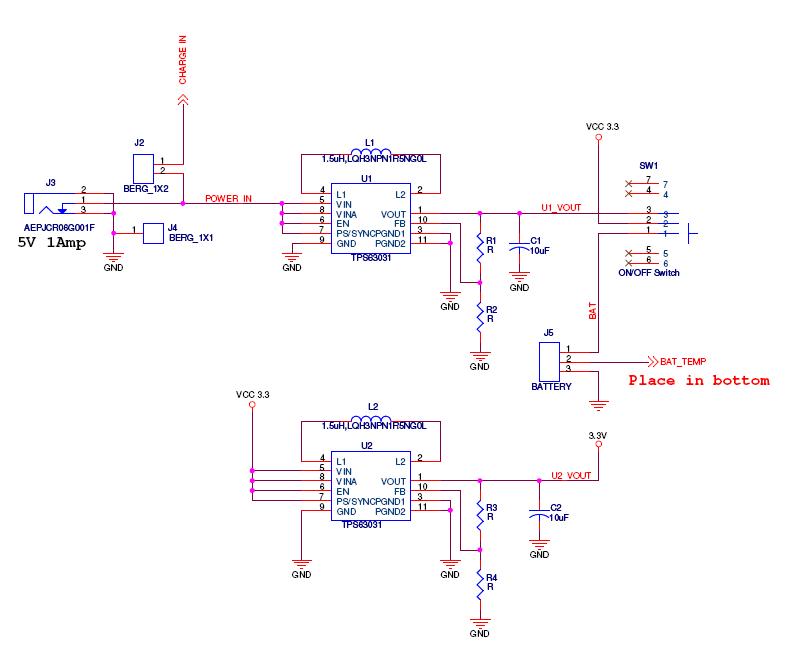
I'm using TPS63031 for my system to provide 3.3v regulated ouput . I used the same circite which is given in page no 1 of datasheet.

I have given 3.6 v as a i/p source to TPS63031, and at the place L1 inductor(from data sheet ) i have connected  1.47A  inductor from murata(LQH3NP) . 

And now the problem is, its consuming more current about 12mA . my system consumes only 2mA ( I tested this by providing 3v directly to my system ).

Why its consuming more current ...? what is normal current consumption of this TPS63031..? 

regards

chethan

  • The circuit on page 1 of the datasheet has PS/SYNC tied high.  This will disable power save mode.  For reduced current consumption at low loads, tie this pin low instead.

  • Hi ,

    thanks for the information .

    The maxium current cosumption of my load will be 50mA(this 4 sec in an hour) .  so is it a safe to put the tps63031 in power save mode..?

    and what is the ideal current cosumption by the TPS63031 itself..?


    regards

    chethan


  • Yes, the TPS63031 can always be operated in power save mode safely.

    I believe you desire to know the input current to the TPS63031.  Is this what you want to know?  This can be found by looking at the efficiency graphs in the datasheet.  Input current is output power (Vout * Iout) divided by the efficiency at your operating point (Vout, Vin, Iout).  Take this calculation and divide by the input voltage and that is your average input current.

    With your 165 mW load, and the efficiency at that point being roughly 93% (from figure 5), at 3.6V in you get 49 mA of input current.  Your results may differ slightly from this due to the different inductor you are using and part to part variation.

  • Hi Chris,

    Thanks for information .

    Actually I want to know the current consumption of the internal  circuit of TPS63031 while doing the busk-boost operation ..?

    And can you suggest right inductor ..?

    regards

    chethan

  • The datasheet details the selection process for the inductor on page 14.  The inductance should be between 1.5uH and 4.7uH and a list of recommended inductor families is given in table 1 on page 15.

    The quiescent current is the non-switching supply current consumed by the TPS63031 and is specified on page 3 of the datasheet.

  • Hi Chris,

    I'm facing some problem with TPS63031..

    my new design consists of two TPS63031, as shown in the attached schs.

    I'm provinding a supply of 4.2v ,800mAh.. but I'm not getting the proper voltage at the output of IC U1(first regulator ) and nothing at the U2 . Just getting 0.3v at V1out.

    what may be the problem .  I need 3.3v at the output to run mu system..I'm using standard inductor which is specified in the datasheet (i.eLQH3NPN,1.4A ),

    since I dont want any voltage devider so I sorted FB to Vout put. by '0'ohm at the R1 and R2 is open (from schs)  .


    regards

    chethan


  • You have no input capacitors shown on the schematic.  These are required for each regulator to function.  Please see the datasheet for the recommended value.  Each regulator needs their own input capacitor, placed right next to the IC.

    You can also order the EVM for the TPS63030 and evaluate it first.

  • I also see that your schematic shows the output capacitor drawn as a tantalum or electrolytic.  I recommend ceramic output capacitors.  If  you choose a tantalum or aluminum electrolytic, please place a high quality ceramic capacitor directly at the output of the TPS63030.  Please refer to the capacitor selection paragraph for more details on capacitor selection.  It is very important that the input and output capacitors are properly placed and routed on the PWB.  Please refer to the EVM for guidance.

  • Hi,

    It was drawn as tantalum cap but i used ceramic capacitor only on the board ..

    I tried the output by removing the capcitor also . but its giving same output as 0.3v  ...

    Actually I got assembled 4 boards but all the boards are in same condition .

    What may be the problem pls help.


    regards

    chethan

  • Hi,

    I externally connected the  ceramic 10micro F capcitor at  the i/p of regulator  ,

    still its showing same at the o/p i.e 0.3v.

    pls help..

    regards


    chethan

  • The IC requires both an input and output capacitor to function.

    You need to debug your circuit piece by piece.  First, make sure that all your solder joints are good and that there are no shorts between the pins on the board.  Ohm out each pin to make sure they are connected to what you think they are connected to.

    Look at VIn with a scope.  Make sure it is DC and stable.  Supply Vin with a lab supply and make sure the lab supply is not current limiting.  Disconnect any loads.

    Next, is the IC switching?  Look at L1 and L2 for any signs of activity.

    etc.

    You can order the EVM and evaluate its performance to get a feel for how these ICs operate.  The EVM is fully tested and will work.