This thread has been locked.

If you have a related question, please click the "Ask a related question" button in the top right corner. The newly created question will be automatically linked to this question.

TPS92692EVM-880: trouble shooting for TPS92692EVM-880:can't get the output current

Part Number: TPS92692EVM-880

Dear sirs,

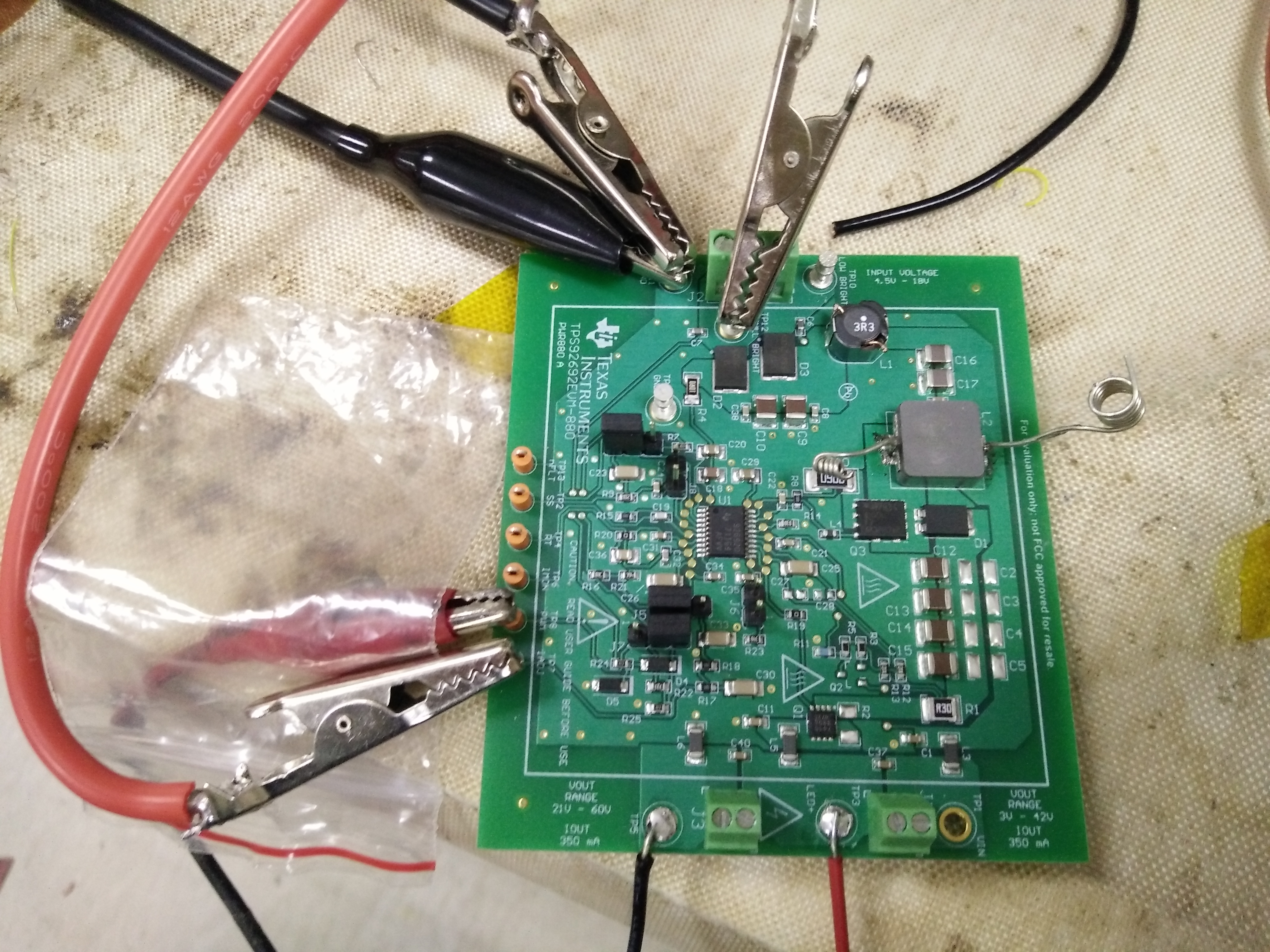
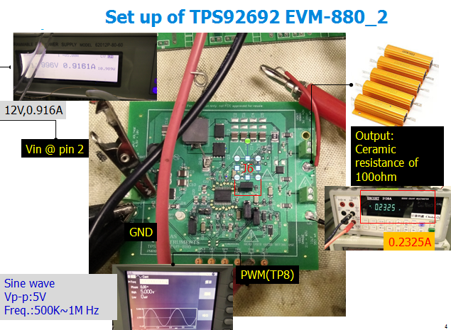
We have evaluated the EVM board(TPS92692EVM-880) for automotive LED lighting application.

However, we could just boosted from 12 to 55~60V but couldn’t get any output current(the default is 356 mA).

Can you kindly help to provide any advice?

  • Hello Bob,

    You mean you get zero output current or not the full 350mA of current? Did you test it with a lower voltage LED stack and it worked fine? What is your load exactly? What kind of supply are you using? Does it have enough current for that power level? Have you made any modifications to the board? There isn't much information to go on here, but I will try and help if you could give some more details. Thanks.

    Regards,

    Clint

  • dear Clinton,

    thanks for your feedback.

    (1)You mean you get zero output current or not the full 350mA of current?

    -->yes, you are exactly correct.

    (2) Did you test it with a lower voltage LED stack and it worked fine? What is your load exactly?

    -->actually we didn't use LED string as the output load but use electrical load which draw out current automatically depending on the output voltage( in my case is 60 V). the electrical load is shown as below,

    (3)What kind of supply are you using? Does it have enough current for that power level?

    -->the input power supply is shown as below, which provided 12V and 10A(if over the EVM limitation, the power supply can adjust the current)

    in addition, to achieve direct PWM dimming, we connected the shunt across pin1 and 2 of J7 and apply 5V(1KHz square wave) to TP8.

    the whole setup is shown as below,

  • Hello Bob,

    This second setup looks a little different than the first one. So that leaves me with 3 comments, hopefully one or more will help you:

    1. The input voltage should be applied to the "FULL BRIGHT" test point (or center pin of J2).

    2. It looks like you are trying to synchronize the switching frequency. What frequency are you using? It's hard to read, but it looks like your thresholds are right on the edge, you may not even be syncing. I would put the low level at <1.8V and the high level at >3.1V so you are sure you are exceeding the rising and falling thresholds.

    3. If neither of those helps I would try an LED load (or a simple diode load, 3x1V diodes in series for each "LED"). I have seen numerous issues of electronic loads not behaving correctly with LED current regulators.

    Let me know if any of that helps. Thanks.

    Regards,

    Clint

  • Dear Clint,

    Thanks for your advises.

    First We have changed the input voltage from pin 1 to pin 2(full brighness).

    Secondly  apply external PWM signal at TP8 with sine wave(Vp-p 5V,500K~1MHz).

    Thirdly we used ceramic resistance(100ohm) instead of electrical load.

    the set upt is shown as below.

    thanks for your favor.

    we have been successful to get the output current.

  • That is good to hear! I will go ahead and mark this "TI thinks resolved" so that it can be closed out. Feel free to post here if you have further questions, closing it out will not prevent more posting and it will notify me. Thanks.

    Regards,

    Clint