This thread has been locked.

If you have a related question, please click the "Ask a related question" button in the top right corner. The newly created question will be automatically linked to this question.

UCC28089: Multi-purpose P-P Converter help.

Part Number: UCC28089

Hello,

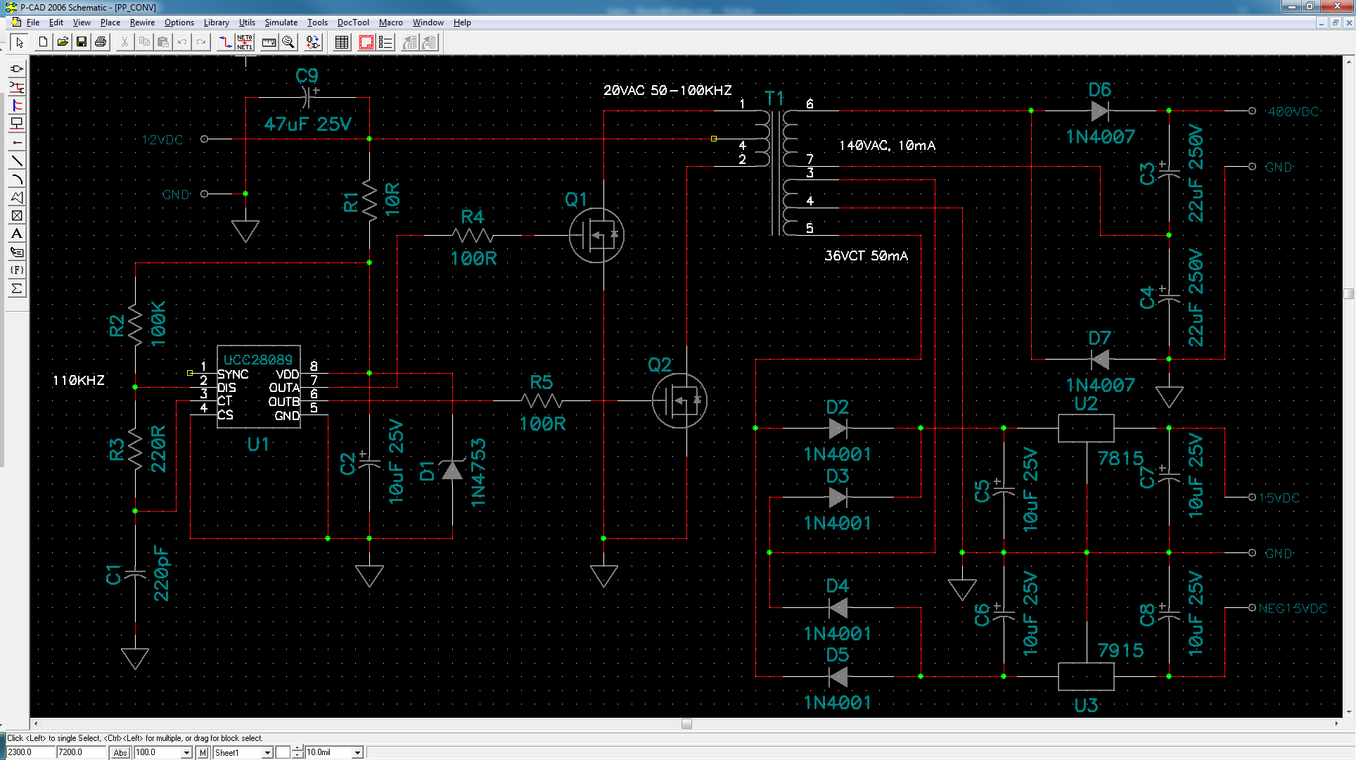
I'm considering using a simple P-P converter for a power supply project.

Vin: 12VDC Regulated, up to 1A.

Vout 1: 300VDC, 10mA.

Vout 2: +/- 15VDC, 50mA.

Since the input voltage source is already regulated, I don't think I need flyback regulation. 

I've made some progress using the UCC28089, but I could use some help optimizing it in the following ways:

1) Suggested mosfet and coupling resistor value.

2) The high voltage secondary feeds a voltage doubler. Please suggest any HF filtering that may be required and advise adequate filter capacitor value.

3) I was considering using standard 3-pin linear regulators on the bi-polar 15 supply, mainly for filtering out noise. Is that overkill and is there a cleaner/simpler suggestion? I have additional board space and room in the budget as long as it doesn't get too out of hand.

I've had a preliminary transformer made with a primary DCR of about 0.4 ohms. Right now I'm getting +/-18VDC (before the regulators) and about 280VDC no load, 

Current draw from the supply source is around 90mA. As soon as I start loading the supply, roughly 30-mA on the bipolar side, the output voltage drops to +/-10VDC even though the input draw goes up to around 150-200mA. That also pulls down the HV secondary supply voltage around 30VDC, so I think my problem is on the drive side. 

Thanks,

Steve

  • Hi Steve

    I'm curious - what do you mean by 'P-P' - I haven't heard the term before.

    With the timing components you have selected you should see a switching frequency of about 213kHzThe 1n4001 diodes you have selected have a very long reverse recovery time and they are not suitable for operation at this frequency. In fact they are normally only used at line frequencies (50/60Hz). I would suggest that you change them to a fast rectifier - a 1N4148 should work ok for the ±15V outputs - it has a 75V breakdown voltage. The BYV29C is a 600V, 30ns diode and should be ok for the 400V output. I am not saying that either of these diodes is optimum, only that they should work and allow you to make some progress.

    100 Ohms is probably a reasonable starting point for the driver resistor. The MOSFET choice and the effort you spend on selection depends on a lot of factors. How many units will you build, are there mechanical constraints on the package. In general, at this power level I don't think the choice is very critical.

    I would also suggest that you add a 10k resistor from gate to source of each of the primary side MOSFETs. The purpose is to make sure that the FETs are off if for some reason the controller outputs go high impedance (100R resistors going open circuit for example)

    You may need a second stage filter to suppress switching noise and ripple. I can't offer component values but you should think about a LC filter with a resonant frequency of about 20kHz. You should also look at adding some high quality (X7R or better) ceramic or film capacitors across the output electrolytics because the electrolytics impedance will tend to increase at higher frequencies.

    Regards
    Colin