This thread has been locked.

If you have a related question, please click the "Ask a related question" button in the top right corner. The newly created question will be automatically linked to this question.

UC28025: Inquiry to use SS pin to disable PWM

Part Number: UC28025

Hi Team,

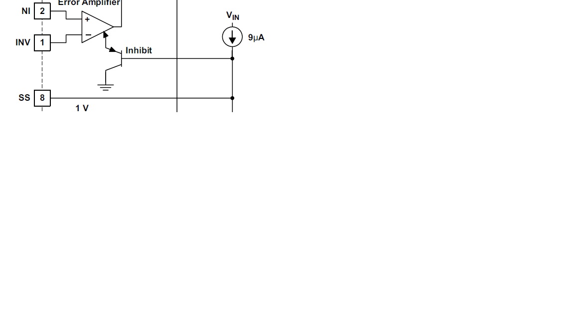
I got an inquiry from my customer on the UC28025 if it can be disabled (i.e. no PWM coming out of pins OUTA/B) by pulling the SS pin down to around 0.7V?

Or how low must the SS pin be in order to guarantee that the PWM IC is disabled?

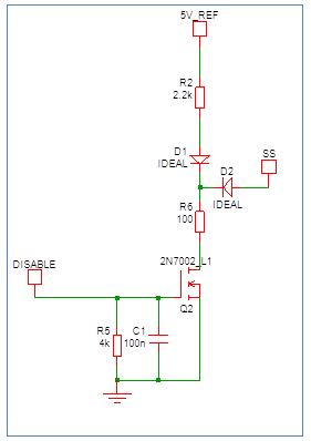
They plan to use the circuit below.

Note that the 5V_REF comes from the UC28025 VREF pin.

Thanks! 

Best Regards, 

Alfred Logico

  • Hi Alfred,

    Thanks for your interest in UC28025. The SS pin will limit the maximum duty cycle and when pulled low enough, should limit the device to 0% duty cycle. Alternatively, Your customer could pull the ILIM/SD pin to above 1.4V which will shutdown the device.

    Best Regards,
    Ben Lough
  • As per my understanding, I would suggest pulling the SS pin to GND, as it is not very clear from the datasheet the minimum value of SS pin to guarantee an OFF state. The design team would be able to help you better, but for a quick solution pulling SS low will disable the Switching.

    As a warning, pulling down SS pin does not mean the PWM is in OFF state. Any noise in this path may result in PWM trying to switch.
    The PWM controller will be in ON state/Active as long as there is a Vref.

    I hope that was helpful.
  • Hi Sonal and Ben,

    Thanks for the response, an additional question since I believe it wasn't answered, what is this voltage range of the SS pin that the PWM will be considered disabled? I know this info is not in the datasheet, but this is critical to the circuit design.

    As seen on the schematic, they will supply the Vgs of Q2 to pull the SS pin to ground in an attempt to disable the PWM.
    However, the SS pin will most likely be around 0.5-0.7V due to the drop of D2 and of R6.

    Can you confirm at around this voltage, the PWM will shut down?

    Thanks!

    Best Regards,
    Alfred
  • I was hoping to follow-up on this. I hope someone can get back to me asap. :)

    Thanks!
  • Hello Alfred,

    The SS pin needs to be pulled below the V(BE)  of the inhibit transistor  to ensure PWM is disabled.

    You can see this from the "inhibit " section of the functional block diagram in the data sheet Section 8.2 :

    So D2 and R6 will cause an  issue with shutoff of the PWM.

    My suggestion is that D2,R6 along with R2,D1 and 5V_REF are not needed and can be removed.

    You can connect the MOSFET directly across the SS pin since the soft start charge and discharge current is limited to 9uA and 7.5mA respectively.

    What you do need to add  is a soft start capacitor from SS to ground .

    Even if it is just a small capacitor that produces a fast startup, it is best not to leave the pin open circuit.

    Regards

    John

  • Hi John,

    Thanks for helping answer! I just have a follow-up to this. I hope you can help answer below:

    R2 and D1 are required for another part of the circuit. I just showed them in the schematic in case you may see a problem with the 5V_REF pin being loaded as such. Will this be a problem for 5V_REF?

    We can probably remove D2, but we might need to retain R6 or decrease its value. For this reason, what is the worst case minimum Vbe of the SS pin? I cannot seem to find it in the spec.

    There is a 100pF cap on the SS pin, I just did not show it in the schematic.

     Thanks! 

    Best Regards, 

    Alfred Logico

  • Hi Alfred,

    If you remove D2 the max voltage on the SS pin is about 200mV when disable is activated (R6 = 100 Ohms.)

    The voltage on SS needs to be maintained below 0.5V at room temp to ensure the PWM is off.

    So with D2 removed the ic can be disabled.

    You can decrease the value of R6 or increase the value of R2 to further decrease the min voltage on SS pin.

    R6 is going to force a current into the SS pin and this current needs to be less than 5mA  so 2.2kOhms is a good value
    Also D1 is required because the absolute max voltage on SS needs to be less than VREF + 0.3. and it is good to have some margin here.

    Hope this helps

    Regards

    John