


Other Parts Discussed in Thread: TIDA-00443
Hi
We have built an PFC converter based on TIDA-00443-230V, 900W, PFC with 98% Efficiency for Inverter Fed Drives Reference Design.
The same circuit has been reproduced without any changes. While testing the circuit in the boost follower mode, we observed the following issues.
Initially the MOSFET failed.
Then the AC input to the PFC is given from an auto transformer . PFC ON and bias is shorted together and connected to an external 15V DC supply.
(Note :For Boost Follower Configuration: Populate R14 and Q4 and set R9 = 21.5k Populate R5 = 0.2 Ohm, this has been followed)
The diode D10 is removed since it energizes the relay at the start and bypasses the 10 ohm resistor. Even after this we found that the when the o/p DC voltage
reaches around 55 Volts DC the gate pulse starts with > 95% duty cycle and the o/p voltage boosted to > 600 V DC.
Following which the MOSFET is removed and the o/p voltage DC ( now same as the i/p DC voltage is increased till 330 V DC) It is found that the gate pulse
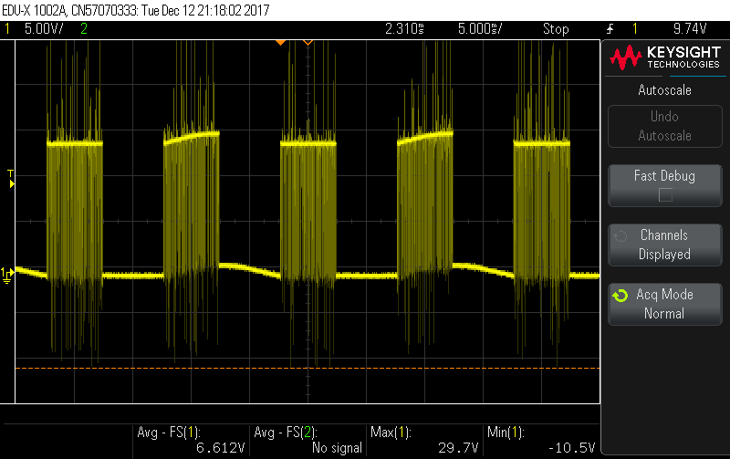
remain to be same with a duty cycle of >95 %. Once the voltage is increased beyond. 369 V DC. The gate pulse was 0 for approximately half cycle ( 50 Hz frequency)
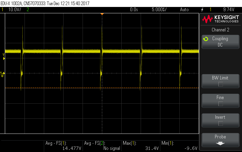
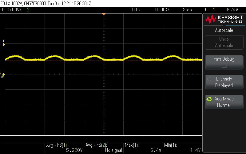
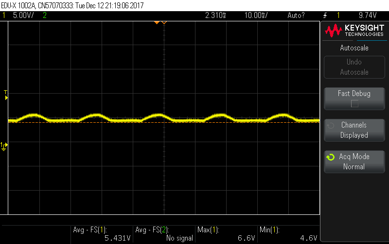
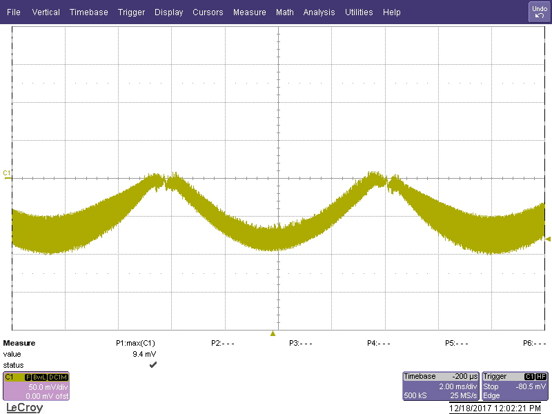
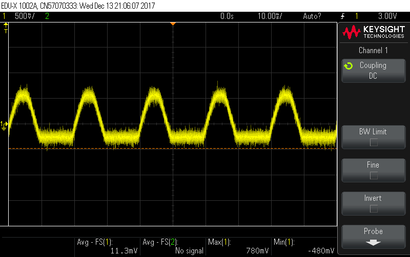
and once again 90 % for the remaining duration. Then the Vsense waveform was observed. It is found that the Vsense is not a pure DC and comes with a ripple @ 100 Hz.
It seems whenever the Vsense crosses 5V, the pulse gets shut down and whenever it is less than 5 V, the gate pulse remains at 95 %.
I guess V sense shd be a ripple free voltage and I'm not sure why Vsense is having such a waveform. I have also attached the waveforms of Vsense and Gate pulse
for a voltage of 340 V and 370 V. Kindly help to resolve the issue.
Thanks
Lenin.


