This thread has been locked.

If you have a related question, please click the "Ask a related question" button in the top right corner. The newly created question will be automatically linked to this question.

LM5085: Strange behavior while increasing Vin

Part Number: LM5085

Hi! I have a strange problem with LM5085 in production PCB, wondering what could possibly go wrong here.

PCB has 3 DC/DC converters (all of them with LM5085) - +5V, +3V8, +3V3. All of them created in webench with Vin range around (9...36)V. Before that trouble appers we've used 12V to supply the PCB and everything worked properly.

But when i've tried to supply PCB with 24V I've found that +3V8 rail began to fail. Futher research showed that it's not a current limiter (replaced Radj with 100k). Under medium load (about 400 mA, DC/DC calculated for 4 Amps)  there is random voltage drops about 1V down.

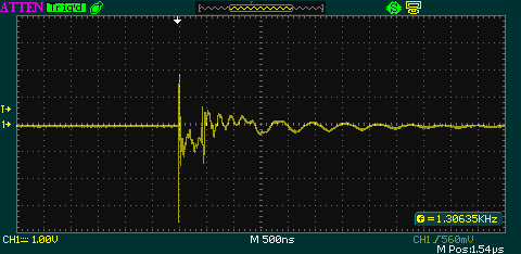
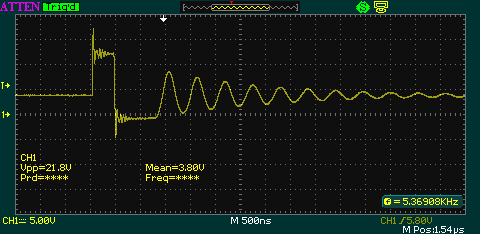
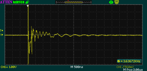
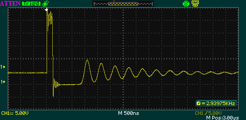
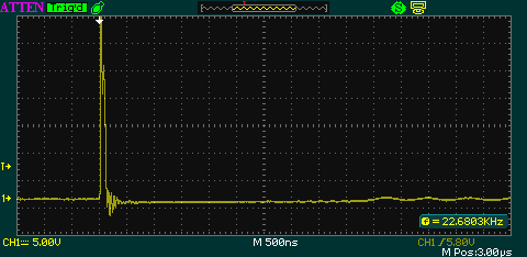
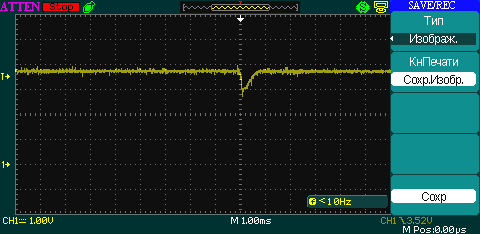
Here how +3V8 looks without load (Vin=24V):

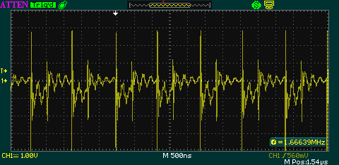
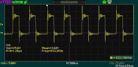
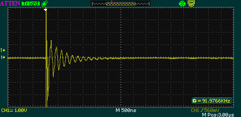
Here how looks +3V8 with 10Ohm load (Vin=24V):

Same trouble exists in +3V3 power source (but it's designed for 0.5 Amp load).

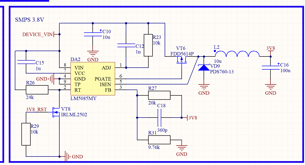
Here is my schematic (currently R23 replaced with 100kOhm):

Any thoughts what possibly could go wrong?

  • Hello Vasyl,

    Could be a caused by a number of things?

    Is it possible for you to measure the switch node waveform, left side of L2?  also can you place a current probe in series with L2 and measure the current through L2?

    I would like to see 2 or 3 switching cycles if possible.  Thanks.

    David.

  • Hi David, thank you for your respond!

    I've added 0.51Ohm resistor as a current probe in series with L1 (So I_L is a voltage across 0.51Ohm). Here are waveforms:

    I_L without load (Vin=12V)

    I_L with 10Ohm load (Vin=12V)

    V_SW without load (Vin=12V)

    V_SW with 10Ohm load (Vin=12V)

    I_L without load (Vin=24V)

    I_L with 10Ohm load (Vin=24V)

    V_SW without load (Vin=24V)

    V_SW with 10Ohm load (Vin=24V)

    I'm very confused with I_L @ 12V because there is no chance CCM could look like this. Maybe there is some trouble with solder joints' quality or with tantalum caps?

  • What else I've tried for now:
    1) Different inductors: 5.6 uH, 18 uH, 33 uH. Minimal waveform differences comparing to 10 uH (also doesn't work with Vin=24V)
    2) Adding 100uF C_IN (zero effect)
    3) Adding 100uF C_OUT ("light load" changed a bit, but still doesn't work on 24V).
  • Hello Vasyl,


    I am not sure that your current measurements are measuring the inductor current correctly, as there appears to be a lot of noise.  You may clear things up if you measure differentially across the Current sense resistor using a kelvin sense connection (short leads to the Rsense). 


    Having said that the voltage on the Switch node look fine. 


    can you capture the Vswtich at the time the dip occurs?

    I am thinking the load is pulsing causing a dip to occur on Vout???


    Hope this helps?


    David

    ,

  • Hi David!

    Sadly I don't have an opportunity to set up a proper current measurement for now. What I was able to do:

    1) Replace current sensor with 0.1 Ohm

    2) Minor PCB rework

    3) Oscilloscope adjustment (including software lowpass filtering)

    After that I see next waveform of I_L (Vin=12V):

    Under Vin=24V waveform is pretty the same (duty cycle is different of course). So for now it looks like I have CCM after all.

    I wasn't able to capture waveforms you've asked properly (very cheap oscilloscope, sorry). What I was able to check - when V_OUT goes down V_SW permanently turns off, so under Vin=24V DC/DC periodically turns off MOSFET switching. Looks like some king of protection but I have no idea which one for the moment. Don't look like thermal protection because PCB is pretty cold.

  • Thanks Vasyl,

    You waveforms look pretty good, including the current in the inductor. You will probably need two channels at least on your scope to obtain more information needed to give you a better response as to what is going on.

    Please confirm that you have a momentary Dip of ~1V on vout, right?

    If so, did you rule out this is not a load current is not stepping to a high load during the vout dip?
  • Yup, that dropout is about ~1V and it reveals under constant 10Ohm load.

    So, what we have for now:
    1) DC/DC works pretty well with Vin=12V and easily handles ~400mA of constant current (checked with 10Ohm resistor as a load) or 2A peak (checked with it's actual load which is GSM modem)
    2) DC/DC fails to handle both 400mA of constant current and 2A peak consumption when Vin is equal to 24V (same test conditions)
    3) In both cases DC/DC operates in CCM, current limiter is disabled by replacing Radj with 100kOhm.
    4) DC/DC itself designed to operate with Vin up to 28V and Iout up to 4A (calculated by Webench).

  • Hello Vasyl,

    I am still having a hard time to see how the output would dip under a constant load, unless the loop is unstable? Not having two channels on the scope is making it hard to see exactly what is going on?


    However, upon further review of your schematic, I am struggling to see a design that will be stable, assuming the output capacitor is a ceramic?

    If this is the case, when the design calculations were implemented, did you follow the guidance given in the datasheet, regarding type II ripple injection? Type II = Resr + Cff...

    If not, may I suggest you follow the guidelines and modify in accordance with the guidelines in section 8.2.2.2 and then retest?

    Hope this helps?

    David.
  • Hi David,

    I will try that assume with output capacitor, thanks.

    What else I was able to find - I've found much older PCB (ones from prototypes, 2 layer) with the same DC/DC. It has 3 parts which is different: inductor (5.6 uH, that one I've used in new PCB for tests), Rt=24.9 kOhm and feedback resistors. But that board works perfectly with Vin=24V under both static and dynamic load. Of course first thing first - I'll test a guess with output capacitor, but it will be ok - any chances for troubles with IC revision?

  • Hello again, David!

    Your guess with capacitors was right! I've replaced both Cin and Cout (but I guess problem was in Cout) with ceramic ones and DC/DC works extremely stable (plus - reduced voltage ripple). So seems like problem was in capacitors which our SCM ordered (because older PCB with tantalum capacitors I've used to order by myself also works well).

    Thank you for your assistance, you guys are as always great :)