This thread has been locked.

If you have a related question, please click the "Ask a related question" button in the top right corner. The newly created question will be automatically linked to this question.

BQ40Z60EVM-578: Cell Balancing does not seem to be working for this 2S6P configuration

Part Number: BQ40Z60EVM-578
Other Parts Discussed in Thread: BQ40Z60, BQ40Z50-R2

Hi,

please help shead some light on this issue below...

thanks,

Tom


Can cell balancing be done during Constant Current (CC) mode or during Constant Voltage (CV) only?

What is the most voltage difference that can be balanced in one charge cycle?


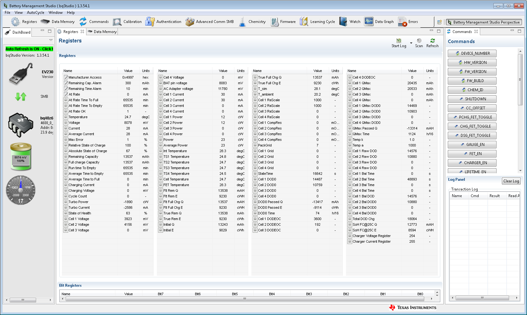
Cell Balancing seemed to be enabled but the bq40z60 did not balance the cells and went into a fault condition at Full Charge.


Senario:

Cell Balancing was enabled by going below 10% RSOC then Resting.

DisCharged to:

RSOC = 3%

Cell 1 =  3343 mV

Cell 2 =  3562 mV


12VDC (AC Input) was applied and charging started.

CB = 1, Cell Balancing = Active

Cell 2 Bal Time = 65535 seconds


Full Charge was reached without going into Constant Voltage mode.

Cell 1 Max Voltage = 4040 mV

Cell 2 Max Voltage = 4300 mV


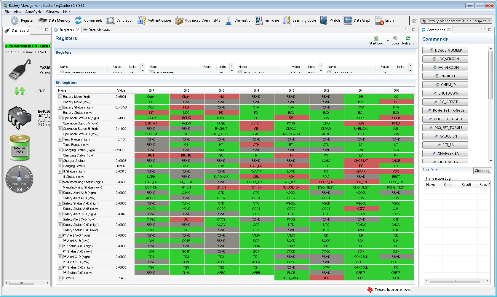
Here are the Bit Registers of concern:

TCA = 1,                Terminate Charge Alarm = Detected

FC = 1                    Fully Charged = Detected

XCHG = 1             Charge FET disabled = Detected

SS = 1                   Safety Mode = Detected

CHG = 0                Charge FET status = Disabled     

VCT = 1                 Valid Charge Termination = Detected

MCHG = 1            Maintenance charge = Detected

TC = 1                  Terminate Charge Alarm = Detected

FC = 1                 Full Charge = Detected

COV = 1              Cell Over-Voltage = Detected

OC = 1                 Flag Over-Charge = Detected

  • Hi Tom,

    We will have to research these questions... however....

    Before you get too far along with your design using bq40z60 we would like to make sure you have considered all of the options as well as the challenges of working with a such a tightly integrated solution.

    We have found that many customers using bq40z60 have difficulty designing their board to pass EMI testing. This is due to the limited degree of freedom you have when laying out such an integrated solution which includes a switch-mode device. As attractive as it may sound to have the charging, gauging, and protection functions in one IC, in practice by using a separate charger and a separate gauge you get more flexibility and it can actually be easier to design. Not only can you choose from a wider range of chargers and gauges, but you can take advantage of newer technology and newer firmware. Popular choices for discrete multi-cell chargers range from standalone ones with integrated FETs like bq2417x or external FETs (for higher currents) like bq2461x to SMBus/I2C controlled chargers like bq2477x, among many others. The newest and most interesting charger is the buck/boost charger bq2570x which allows you to take any voltage input and charge any battery voltage stack, as well as take that battery voltage and boost or buck it back out to any target voltage. It’s great for USB Type-C and USB-PD applications. On the gauge side, the most popular new standalone gauge is bq40z50-R2 which has the most recent feature set and more extensive safety and protection options.

    Of course TI is here to support you no matter which ICs you choose, but be sure to consider all of your options and don’t assume that integration is always the best.

    Sincerely,
    Bryan Kahler
  • Hi Bryan,

    thanks for the fyi's...
    that is alot of info/options to digest before changing course and we will take it into consideration but i believe we will continue with the bq40z60 for now.

    in terms of the Cell Balancing, i'm starting to get a handle after looking at some data and osciloscope traces.

    Seems, the balancing is evey 260mS with an 'On Time' of 193mS (~75% Duty Cycle) of ~14mA (measured).
    The documentation indicates a 66% Duty Cycle (typical) but I cannot find any register setting to alter it or any indication of Balancing cycle time (260mS).
    Is there a memory/register to set the Duty Cycle?

    Also, at this Balancing/shunting current of 14mA (measured) derived from 4100mV/(100 Ohms + 150 Ohms) = 16.5mA (very close), it will take days to balance the 6P cells. Today, the cell voltages are getting closer by ~1mV /Hr.... at this rate, the 202mV gap will take ~202mV/24Hr = 8.4days, is this normal?? and expected?

    Can the 100 Ohms series resistor be removed and left with only the internal FET resistance of ~150 Ohms(??) or would the current exceed the chip power rating??

    Otherwise, what is the external balancing method eluded to in the documentation?
    Would the external balancing/shunt be capable of more current, hense, a shorter balance time?

    Or is this voltage difference in our off the shelf batteries an abnormal situation??

    I have alot of questions/concerns but maybe you can summarize...
    your thoughts would be helpfull on to us on this cell balancing topic.


    thanks,
    Tom