This thread has been locked.

If you have a related question, please click the "Ask a related question" button in the top right corner. The newly created question will be automatically linked to this question.

BQ25703A: bq25703A / Input current oscillation at light load

Part Number: BQ25703A

Hi,

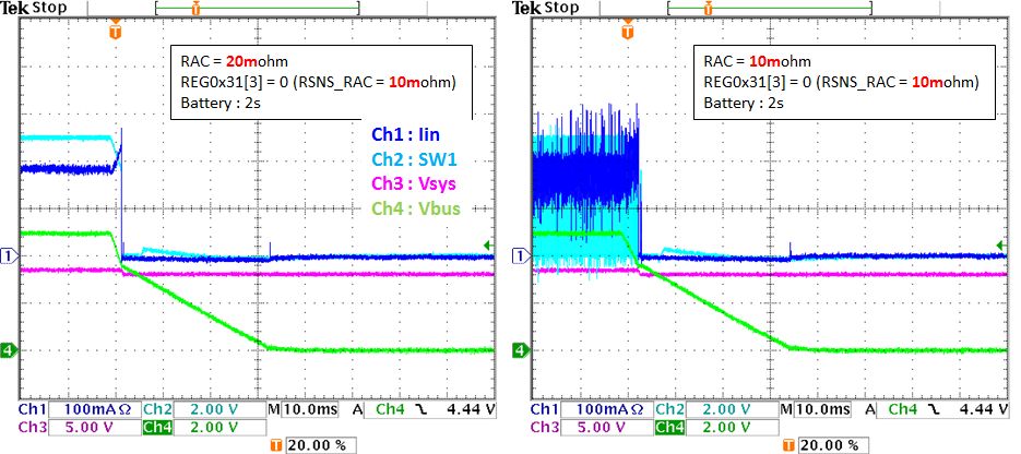
The customer ask that the input current is oscillated at light load operation by using 10mohm for RAC and RSR. And also they commented that this can be improved by changing them from 10mohm to 20mohm.

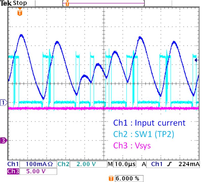
Here is the waveform I checked by using EVM with default external components. I can see input current oscillation as they asked. I'll also try to check with 20mohm but I need more time.

Can you give your opinion if this is proper operation? And also I'd like you to check this on your bench with 10mohm and 20mohm.

[Test condition]

  • Battery : Not connected (No battery)
  • Vin : 5V
  • MinSysVolt  : 8448mV
  • Load : 100ohm resistive

Best Regards,

Satoshi / Japan Disty

  • In bq25703A light load, the converter runs in PFM mode. It is a hysteresis control. When the output voltage is low, the converter starts to burst switching pulse to bring the voltage back. When the voltage is higher enough, the switching pulse is stopped until the output voltage is low again.

    I would say the test waveform could be in proper operation. 10mohm and 20mohm may affect the waveform because bq25703A uses its info for internal control.
  • Hi Wang,

    I continue to evaluate and found that the SW1 is stopped and input current is stable by using 20mohm RAC. After that I also changed RSNS_RAC value to 20mohm in ChargeOption1 Register, then the input current was oscillated again. T

    The customer does not want to see such unstable switching noise, so they hope to use with 20mohm and RSNS_RAC = 10mohm as left in below.

    Can you ask your team again which is proper setting and operation?

    Best Regards,

    Satoshi

  • Changing RAC value to 20mohm and keeping Reg0x31[3] setting to 10mohm makes bq25703A run from PFM into PWM with a lower current. That is why the waveform is different than the PFM waveform at that load condition ( it is not unstable switching waveform. It just a burst mode to have a higher efficiency at light load).

    If move PFM to PWM transition current threshold down by changing RAC value to 20mohm and keeping Reg0x31[3] setting to 10mohm, I want customer to check the VBUS voltage when they remove the input source. Does the VBUS have a remaining voltage when the input source is removed?
  • Hi Wang,

    Sorry for delayed response. I have not received the customer's waveform but I checked it by using EVM. The Vbus goes down to 0V after Vbus is turned off as below. What's your concern if the Vbus have a remaining voltage when the input source is removed?

    Best Regards,

    Satoshi / Japan Disty

  • My concern is: bq2570xA doesn't have inductor under current protection. When the PFM/PWM transition point is moved down and the PFM operation is lost, bq2570xA can allow the battery energy deliver to VBUS. I cannot guarantee the battery energy not deliver to VBUS in all the cases. If the customer did full evaluation and didn't find any concern; converter is stable in all corner cases. They can use the part as they want.
  • Hi Wang,

    Thank you for your support. Let me understand more what you commented.
    Can you explain again the meaning of condition "PFM operation is lost"?

    Best Regards,
    Satoshi
  • It means the converter cannot run PFM. PFM is for high light load efficiency. Each PFM pulse can make the average inductor current is forward. If the converter keeps PWM in no load or very light load and cannot run PFM, we have to make sure bq2570x no remaining voltage on VBUS when the input is removed.