This thread has been locked.

If you have a related question, please click the "Ask a related question" button in the top right corner. The newly created question will be automatically linked to this question.

LM5161: Could you tell me about "how to design LM5161's Inverting-Buck circuit diagram" ?

Part Number: LM5161


e2e.ti.com/.../648215

↑:Based on this thread, I set up a new thread.

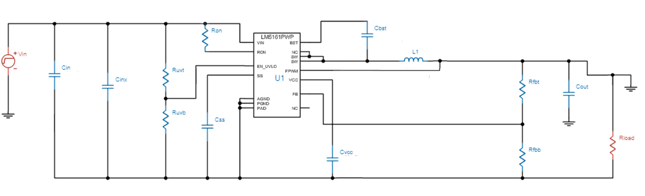
When generating a negative voltage circuit, I will assume the following circuit diagram.


<Specification>

VIN: 20 to 36.6 V

VOUT: -12 V

IOUT: 0.3 A

Can you tell me the setting values of peripheral parts when designing with this specification?

(Please correct even if there is an error in the circuit diagram.)

Best regards,

Masumi Sekiguchi

  • Hello,

    Please use device datasheet for component calculations.

    Following things need to be taken in consideration:

    1. Vimax < Vdevmax + Vout
    2. duty cycle = (-Vout)/(Vin - Vout)
    3. max output current < (Iclmin - Iindripple/2) x (1 -Dmax)

    Other parameter can be calculated as for regular buck converter.

    Please refer to the application mote in the post you refered to at the beginning of your post.

    Best regards

    Brani