This thread has been locked.

If you have a related question, please click the "Ask a related question" button in the top right corner. The newly created question will be automatically linked to this question.

LM3421: About Rhsn and Rhsp

Part Number: LM3421

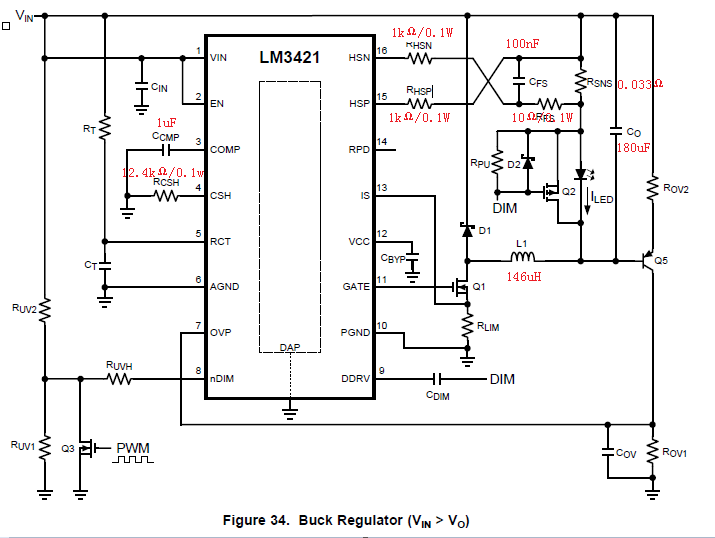
Vin=70V,Vout=60V,Iout=3A
RHSN/RHSP:1kΩ/0.1W

The figure above is from the datasheet of LM3421. The problem is that when I turn on the power, there is about 10% chance that the RHSN and RHSP be burned down.

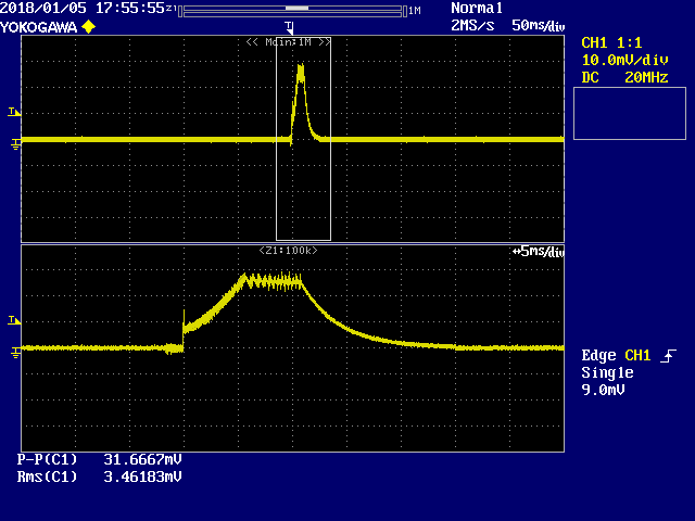
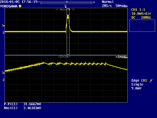
The folloing figure is the waveform of Iout when it happened.

(1DIV=1A)

Accroding to these figures, Iout is lower than 3A and a few seconds later,Iout becomes 0A.

But in normal circumstances, Iout will soon rise to 3.03A , and lasts for a long time.

Could you tell me why RHSN and RHSP often be burned? Is it because the rated power is too low?

-----------------------------------------------------------------------------

Addition(2018/01/15):

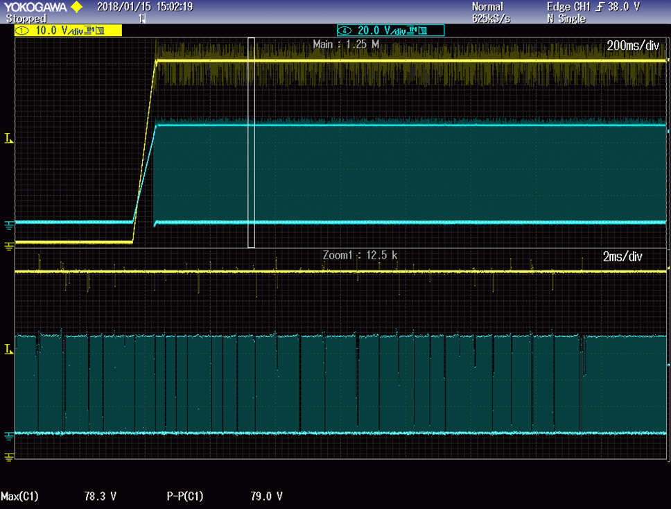
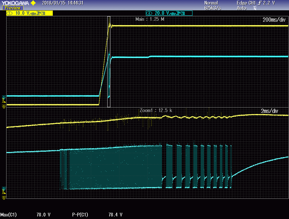
It seems that the circuit of over-voltage protect is in problem.

ROV1 9.1
ROV2 460
COVP 47 pF

1. When the circuit of over-voltage protect circuit  is deleted:  50 times Power ON test, OK.

2. When the circuit of over-voltage protect circuit  is still here : the RHSN and RHSP be burned down (about 10% chance).

I think it is that because the loop ‘Over-voltage protection→ return to normal’ is always been repeated, then  RHSN/RHSP was burned.

But I don't think know why. Could you tell me the reason?

And there is always a strange beap when try  to measure the  RHSN/RHSP's voltage. So I can't get the waveform of it.

Could you show me the normal waveform?

  • Hello Zhun,

    This is not an issue I have seen before but that is the likely reason. You are already running them at the max 0.1W so any transient, such as at startup, may push them beyond their limits. It's easy to test, just replace them with higher rated resistors and see what happens. Generally I give a good amount of headroom, so if you have 0.1W burning in them I would go with at least a 0.125W resistor, but likely even a 1/4W resistor if I have the PCB room for one. If that doesn't solve it there must be something else going on to investigate.

    Regards,

    Clint

  • Thanks for your reply!
    Could you provide me for more information about how to calculate the current and the power of Rhsn and Rhsp?
    Because this looks like a probability problem. So it is better to calculate it accurately, I think.
  • Hello Zhun,

    I am sorry, I completely miscalculated. You should be just fine with 0.1W resistors. The current through them is the CSH current, in this case 100uA. So the power dissipated in them is 100uA^2*1kohm, or 10uW.

    So having said that the only way to damage them would be if the CSP/CSN pins broke down due to over-voltage.

    How are you applying the power? Can you probe the CSP pin during your startup? You have a high input voltage, pretty near the abs max rating, so if the power is applied very quickly (very fast supply, hard plug, etc...) you could have an input voltage overshoot that is causing the pins to break down.

    Is it just the resistors that are damaged or is the IC as well? The IC pins could break down briefly without damage and still damage the resistors, but the IC may have sustained damage.

    Regards,

    Clint

  • Thank you for your support.
    I have added some new data at the beginning of the post.
    It seems that there is a problem with the over-voltage protect circuit.
  • Hello Zhun,

    OVP can be tricky when you are operating so close to the abs max voltages. It will have delays and it can cause some oscillation that as you can see causes voltage overshoots. This must be what is happening because the only way to damage those resistors is if the HSP/HSN pins ESD structures break down so you get a high voltage/current across them.

    Regards,

    Clint