This thread has been locked.

If you have a related question, please click the "Ask a related question" button in the top right corner. The newly created question will be automatically linked to this question.

UCC2895: UCC2895: RAMP and CT current discharge for frequency generation

Part Number: UCC2895

Hi,

The current discharge of RAMP circuit is specified on page 5 of  the datasheet: I_R(sink)=12mA min and 19mA typical.

Which parameter influence the dispersion of this discharging current?

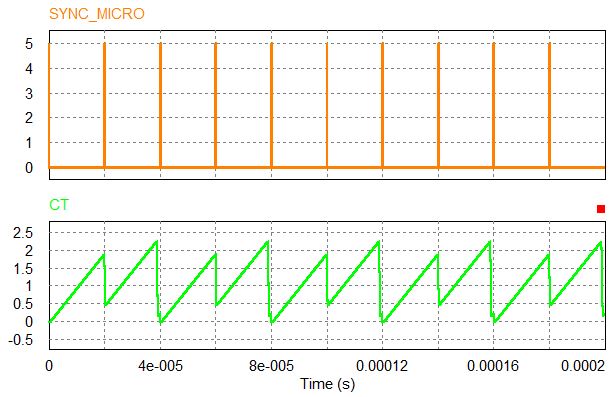
Moreover, in case CT and RAMP are not connected (in peak current mode control for instance), what is the current discharge value of pin CT?

Regards,

Yves.

  • Hello Yves,

    The RAMP Sink current is determined by the Rdson of the internal FET marked in red.

    Another point: If RAMP and CT are not connected then there is no current at RAMP pin, thus no sink current. Please correct me if I understood it wrong.

    Kind Regards,

    Sonal

  • Hi, thank you for answering.
    In case RAMP and CT are not connected, the second question was about CT current discharge. This point is not specified in the datasheet.
  • Hello Yves,

    Let's think of it this way:

    and the discharge current is a function of the discharge FET Rdson resistance. But the maximum recommended Ct is 1000p and the minimum discharge time is about 100nsec and the oscillator ramp size is about 2 volts. 

    So using this equation we can say that discharge current must be more or less close to 20mA.

    I hope this helps.

    Sonal.

    Please hit Answered if you are satisfied with the response.

    Thanks.

  • Hi,

    where is the minimum discharge time specified? is it the 120ns to add in the Tosc calculation?

    Secondly my first concern was about the current discharge dispersion (or Rdson of discharging FETs).

    I am planning to use an external signal to generate the clock of the UCC2895 using SYNC input. I set Rt, Ct, and SYNC pulse width to get the correct Ct signal. But this configuration is ok for typical operating conditions,  Idischarge=20mA. Below is what I measure:

    OK.

    But due to dispersions, the minimum discharge current can be reduced by half and reach 12mA as specified in the datasheet. In this case, the CT signal simulated is given below:

    Ct signal is not stable. ( I implemented UCC2895 model based on block diagram and Oscillator block diagram given in the datasheet )

    It is necessary to set the Ct, Rt values and SYNC pulse width to cover Rdson variations, but the dispersion is to wide.

    So I need to know which parameters mainly influence the variation of  Rdson of the discharging FETs.

    I guess the main contibution come from manufacturing dispersion, temperature change (-40°C to +85°C in my case) and steady state Gate signal voltage. 

    Is it possible to get the detailed contribution of all those parameters so I can set the good couples of Rt, Ct and SYNC pulse width for my application, please?

    Yves.

  • Hello Yves,

    I would like to point you towards the application notes and user guides available on the web for the controller, which should have all possible data regarding your design.

    The discharge time is a function of the internal FET of the controller as I have already mentioned. Hopefully, this data will be helpful.

    Sonal

  • I have already checked all the informations concerning the UCC2895 on your website and could not get the information I want.

    I understood that the discharge time is a function of internal FETs Rdson, but know I only want to know the parameters which influence this current variation... 12mA to 19ma is a wide variation range...

    Yves
  • Hello,

    Could you get more informations about the main parameters which influence the Rdson dispersion?

    Yves.
  • Hello Yves,

    The Discharge current is dependent on the Rdson of the internal FET, which can not be disclosed. Since you are running a simulation I would suggest using hit and trial method to stabilize CT waveform. 

    Kind Regards,

    Sonal