This thread has been locked.

If you have a related question, please click the "Ask a related question" button in the top right corner. The newly created question will be automatically linked to this question.

TPS40170: Low side Mosfet getting hot

Part Number: TPS40170
Other Parts Discussed in Thread: CSD18543Q3A

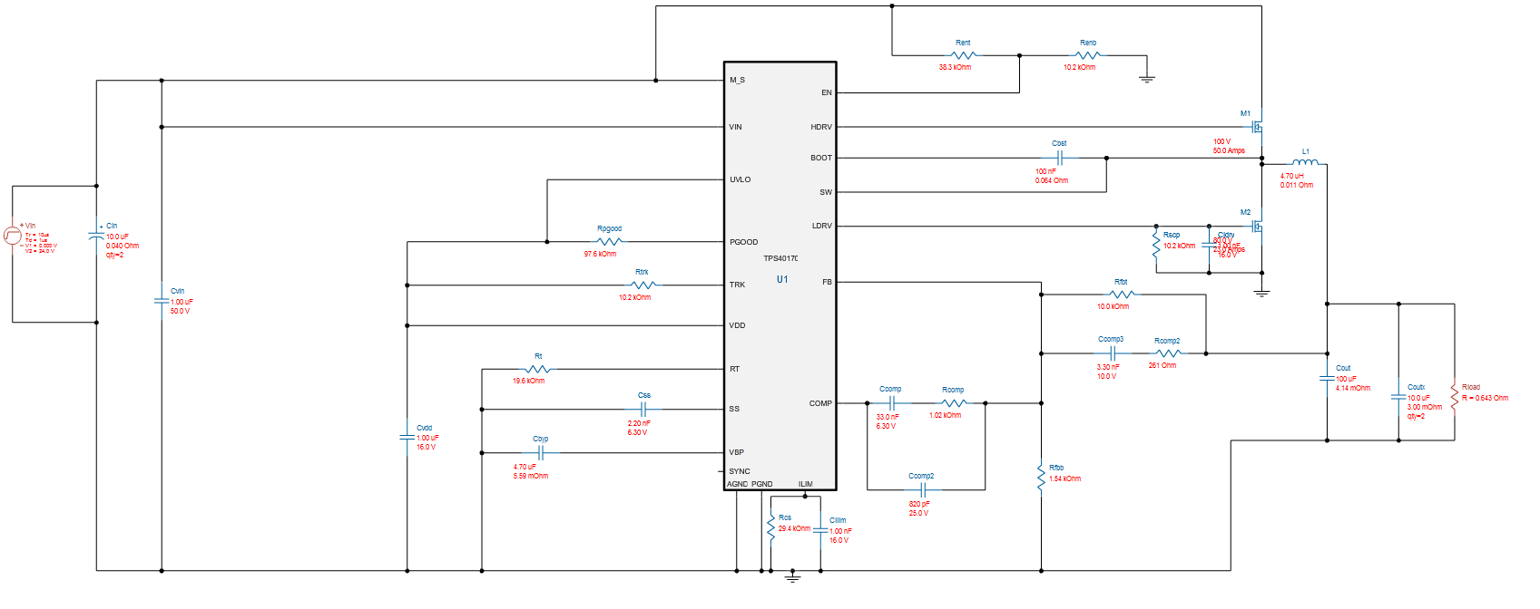
I'm using the TPS40170.  I designed it in webench.  Input voltage is 10-36V, output is 4.5V at 7A max

I have my design up and running.  Initially I had problems with switching noise getting on the high side mosfet gate causing occasional short circuits (as both mosfets were on) at certain input voltages.  However, some extra low value ceramic capacitors on the input power rail near the high side mosfet fixed this by removing noise.

Now all seems to be working, however my low side FET is getting hot.  At 12V it is around 90*C, and at 24V it increases to 110*C approx.  Attached is my circuit diagram.  The thermal simulations I have run, show the low side FET being a lot cooler (80*C max - no fans).

Low side FET = BSC340N08NS3-G

High side FET = CSD18543Q3A

I could do with some input on what to look out for to lower my temperature.  I've had to increase the Rlimit capacitor, as at 6.5A it was starting to limit itself, due to the increase temperature in the low side FET.

  • Matthew,

    It looks like WEBENCH recommends a low-side FET with Rdson=15mohm where yours is 34mohms. That may account for some of the temperature discrepancy. Did you chose your low-side FET for the WEBENCH sim? Can you share your WEBENCH file so I can be sure I'm on the same page? (Top right of WEBENCH page, "Share Design - Share with Public - Get new Shareable Link"

    Another big factor is layout. That can have huge effect on performance. Can you share your layout as well?

    -Sam
  • Hi Sam,

    Thanks for the reply.  I've now replaced the low side fet with one with a lower RDSon and its a lot cooler.  Its just the simulation file on webench that threw me.

    One thing I don't understand is section 8.2.2.8 of the datasheet (MOSGET Switch Selection).  It seems to try and make you make a selection of mosfet based on the resistance/capacitance ratio which seems off.  Ideally you are going to want both of these to be low?  So the ratio seems to not work and don't match up to the solutions of webench.

    Right now I'm using:

    High side FET: CSD18543Q3A which will have a ratio of 1.37 (11.1 mohm over 8.1nC)

    Low side FET: BSC117N08NS5ATMA1  (which will have a ratio of 0.91)

    Originally webench had suggested I use the BSC340N08NS3 has my low side fet (ratio of 3).

  • Matthew,

    Yeah, that's the J/K method. The idea is that a larger FET will give lower conduction losses but higher switching losses. A smaller FET will do the opposite.  Somewhere there's an optimal size with the lowest total loss for the operating conditions of the FET. This paper says the way to optimize is to set (switching losses) = (conduction losses) using the ratio of the defined variables J and K. Ideally, total power loss is minimized when J/K=1.

    Of course one FET might have lower switching AND conduction losses than another FET which means this method is really only good for comparing similar FETs (like ones in the same family).

    And now that I'm looking at the equations, I see they don't take duty cycle into account. That's a big factor in selecting Top and Bottom FETs. If you have a low duty cycle, you'll want the conduction losses in the low-side FET to be smaller because it'll spend more time conducting. There are lots of factors to consider and no tool will be perfect. But we do our best to give as much info as we can without overloading the user :)

    -Sam

  • Thanks Sam.

    That helps.  I just wanted to make sure I was on the correct path.

    Interestly I've had to temporarily substitute the Top side FET from:

    TI CSD18543Q3A (as this is out of stock everywhere)

    to

    Infineon BSZ100N06LS3G

    and I'm seeing an increase in temperature of the TPS40170 of about 8-10 degrees.  Whats the reason for this?  I thought it might be poor soldering, but I've tried it on a few boards and it does follow the new high side FET.

    I'm seeing a lot of TI FETS being out of stock right now, with quite long times until they are back in stock (it seemed OK before Christmas).  Is there a problem with a factory somewhere?


    Thanks


    MAtt

  • Matt,

    I took a quick look at the datasheets and from what I saw:

    • Infineon Total gate charge to 10V is 34nC vs 11nC
    • Infineon Theta_J-C = 2.5 degrees/W vs 1.9 degrees/W

    Those look like the big ones, but again it was a quick look.

    I cannot speak specifics on behalf of the FET team but I've read that longer lead times for FETs are expected industry-wide.

    -Sam