Other Parts Discussed in Thread: TPS61087,
Tool/software: WEBENCH® Design Tools
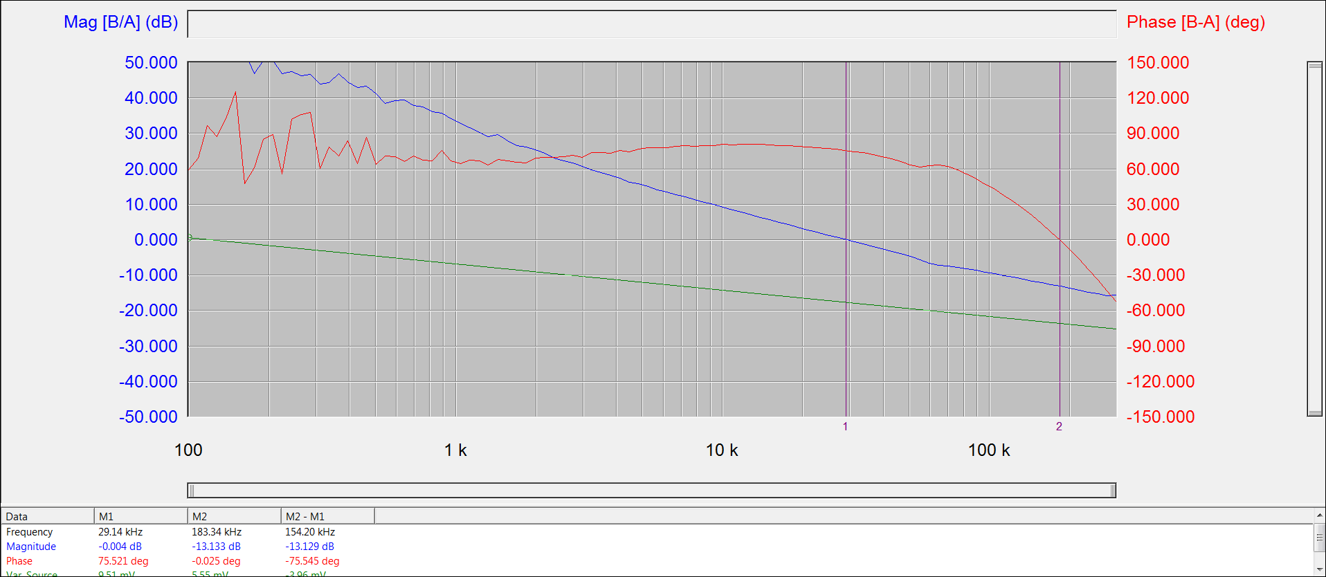
I am running the bode simulation in the webench of the TPS61087-Q1 and see a high Q peak at half the switching frequency, which I would expect if I would have a standard current mode control boost converter with >50% duty cycle and no slope compensation. However, there is no mention of slope compensation in the TPS61087-Q1 datasheet and it also completely disregards this additional pole to consider when designing the compensation network. Further to this, earlier versions of the TPS61087 datasheet explicitly mention that:
"Because of the quasi-constant frequency behavior of the device, the TPS61087 eliminates the need for an internal oscillator and slope compensation, which provides better stability for the system over a wide of input and output voltages range, and more stable and accurate current limiting operation compared to boost converters operating with a conventional PWM scheme."
Thus: Does the model of the TPS61087-Q1 in webench reflect this behavior of the chip in the bode simulation, or does it act as a standard PWM controller and therefore lead to wrong results?
Attached the esim report from webench...
webench_esim_4961223_36_15_328233384.pdf