This thread has been locked.

If you have a related question, please click the "Ask a related question" button in the top right corner. The newly created question will be automatically linked to this question.

TPS54560: Understanding the maximum current limit and current fold-back behavior

Part Number: TPS54560

Hi Experts at TI,

We currently have a design using a TPS54560 that works like a charm. The only thing is that our requirements have changed and we need to see if we can’t squeeze a few hundred more mA out of the design, at least for short pulses < 100ms. We for, better or for worst, have mainly been using what Webench has been giving us. I’ve done maybe a few dozen calculations to make sure what Webench is outputting is accurate, and of course I’ve done physical testing.  

With that in mind I’m trying to get a better understanding of the current limits. I’m assuming that the 5A rating at the top of the data sheet is the max instantaneous current. So it’s at the very most it should be the maximum output current plus ½ the peak to peak current inductor current, and maybe a few hundred mA head room for transient responses. Does this sound right?

I’m also having a bit of trouble figuring out the limits at which the device starts to protect itself from over-current events.  So is it correct to take the equation on Figure 25, and the Current limit threshold in section 6.5, and assume that is the peak current limit, aka the max current the inductor will see if it stays out of saturation? 

  • What is the maximum load current you are trying to get for the 100ms pulse?

    The 5A rated on this device is a maximum DC current rating. The maximum peak current limit allowed by the device is defined as 'current limit' in the Eletrcial Characteristics table on page 6 of the datasheet on ti.com: www.ti.com/.../tps54560.pdf. If the inductor current goes about the current limit, the device will turn off the internal power switch. In extreme over load conditions, there will be frequency foldback protection.

    I cannot find figure 25 and section 6.5 related to current limit on this datasheet.

    The peak current seen by the inductor is the DC load current plus 1/2 of the ripple current. Ripple current can be calculated by equation (29) on page 26. Make sure the inductor rated current is higher than the peak current.

    Regards,

    Yang
  • Thanks for the guidance. And sorry about using giving you the wrong figure. I was looking at the Q1 datasheet. It looks like their are some really subtle differences.  

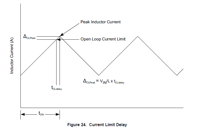
    Any how it was the above diagram. I was wondering how to correctly interpret this. Am I suppose to assume that the tCLdelay starts when the Inductor Current  reaches 'current limit' and the peak current I will see is:

     (Current Limit) + ΔCLPeak

  • This curve shows that the bench measured peak current limit will be slightly larger than the number given in the EC table on the datasheet, due to internal comparator delay. The delay is from when the comparator seen the current limit tripped, to the time when the internal FET is actually turned off. There's a small additional current seen during this delay time, which is the delta-CLPeak in the picture.

    This is not a concern unless you are actually operating in current limiting mode. This should only happen during fault conditions, not in normal operation.

    If your maximum DC load current is not above 5A, you should not see peak current limit in normal operation.

    Regards,

    Yang
  • That clears things up thanks for the help