This thread has been locked.

If you have a related question, please click the "Ask a related question" button in the top right corner. The newly created question will be automatically linked to this question.

UCC24630: DRVpin Pull down function

Part Number: UCC24630

Hello.

I have a question about UCC24630.

Datasheet P5
VDRVST DRV pull-down in start-up

I have a question about pull-down.

1 It is supposed to work at start-up.
  Does it function even when it is stopped?(VDD = voltage below UVLO)
2 If the voltage of VDD is 2 V or less, is the voltage of DRV pin suppressed to 2 V or less?

3 If the DRV voltage is 2 V or less,
  it is considered that a diode is built in the IC between the DRV terminal and the VDD terminal.
  Is the diode actually built in?
  If a diode is built in, please tell me the specifications (MIN, MAX) of Vf and If of this diode

thank you

  • Ishii-san,

    Thank you for your interest in TI here. Let me try to answer your questions.

    1. Yes the pull-down does function when Vdd = voltage below UVLO. From UVLO off to 2V, it uses the strong pull down of 1ohms you see on the datasheet. Below 2V it changes to weaker pull down where the maximum voltage on DRV is 0.95V.

    2. Yes. At Vdd of 2V or less the maximum DRV voltage is 0.95V.

    3. Yes there is a diode between DRV and Vdd. It is not characterized but there is also a clamping circuit from DRV to GND to assist so max voltage stays less than 0.95V when Vdd is 2V or less.

    Even if you use FETs with fairly low threshold voltages this SR controller should be very reliable to keep the MOSFET off during On and Off power states.

    I hope this answers your questions.

    Regards,
    John
  • Hello.

    John-san

    We are conducting evaluations with our circuit.
    Evaluation was also carried out for the DRV terminal.
    I got the result of attachment.
    The voltage of the DRV terminal is less than 2 V as desired.
    However, it was not 0.95 V result.

    Question
    ・Do you know why it is not 0.95V?
    ・May I think that it will be less than 2V?

    thank you.

    UCC24630test.pdf

  • Hi, Ishii-san,

      Thanks for the information. I appreciate the effort you are putting here to put the IC under test and collect all the data.

      In datasheet spec table, you can see


    It sets the limit of 0.95V when the VDD pin is below 2V. At the same time, you can see the test condition is IDRV=10uA.

    In your test setup, you are using 1kohm resistor and 5 to 8V voltage source, which means about 5~8mA of current, which is much higher than 10uA. This pushes the voltage above 0.95V.

    The IC designer tried to provide pull down on DRV pin before VDD voltage is above certain level (normally the Vth of the low side pull down device). If the VDD voltage is low. Before the VDD reaches that level, the low side device can only provide very weak pull down because the internal FET can't be fully turned on. The voltage level could potentially as high as the VDD voltage plus a diode voltage drop.

    Once the VDD voltage becomes above 2V, the pull down FET can get enough gate voltage and fully turned on, then the DRV pin voltage can be kept low even with 5~8mA of current.

    Let me know if this explains what you saw there.

    Thanks.

    Bing

  • Hello.

    Thank you for your answer.

    There are additional questions.

    We want to know when the VDD pin is below 2V.

    For example, The VDD is 0.8V. (ex. VDD is short via external diode.)

    If a voltage is applied to the DRV terminal, we think that current will flow to VDD from the DRV terminal by IC built-in diode.

    So we want to know the "Vf vs. If value" (If below about 10 mA) of built-in diode.

    thank you.

  • Hi, Ishii-san,

      Since this is not the test specs on the datasheet, this would require extra effort to do the measurement.

      Here is the plan. I am going to short the VDD to ground, and apply current source to DRV pin and apply current from external current source from 10uA to 10mA with 100 points.

      And move VDD to 0.8V and do the same exercise and capture the voltage on DRV pin, as two different curves.

      Let me know if this is what you want. This can only be a typical number since I don't have the capability of testing multiple parts. But it'll give you good indication on how the IC behaves.

      I need a few days to collect the material and set up the test bench and will keep you updated.

      Thanks.

    Bing

  • Hi, Ishii-san,

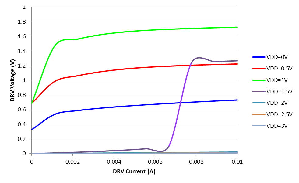
     Sorry for the late response. My source meter went out the lab for calibration and I can only get it done now. Please see blow curve for a typical part I measured under different VDD voltage and different DRV bias current. You can see follow the datasheet test condition, the DRV voltage is always meets the spec.

    When you are testing with 10mA current, you can see the DRV voltage is much higher until VDD voltage is above 1.5V and gate get active pulled low.

    Let me know if you need any further information.

    Thanks.

    Bing