This thread has been locked.

If you have a related question, please click the "Ask a related question" button in the top right corner. The newly created question will be automatically linked to this question.

BQ25898CEVM-730: Output current limit and output gets reset

Part Number: BQ25898CEVM-730
Other Parts Discussed in Thread: BQ25898EVM-730, BQ24298, BQ25898C, BQ25898

Hi,

I am using BQ25898CEVM-730 with EV2300. 

I have connected the 3.9V, 2A power supply to J4, the BAT terminal and measuring output at PMID, J2 terminal connector. Not connected 5V power at VBUS, J1.

I am facing following issues.

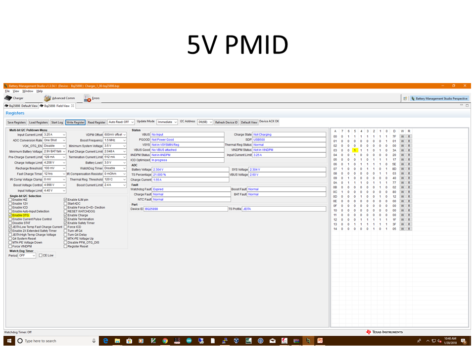
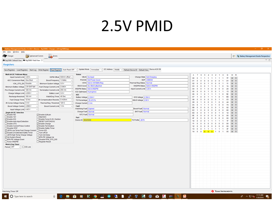
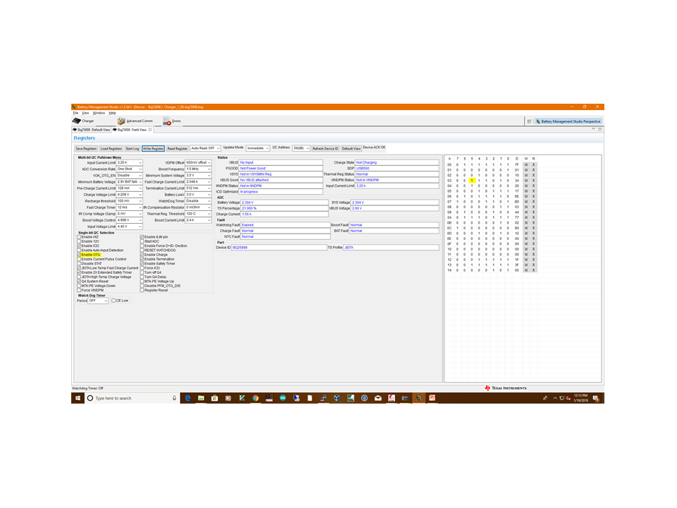
1. When I check Enable OTG in "battery management studio" tool, I get 5V but as soon as I connect a load  (10E, 20W resistor) to this pin, it drops to 2.5V giving only 250mA current.

2. When I remove load, this PMID pin stays at 3.9V (similar voltage to Battery voltage) unless I unchecked and checked Enable OTG again.

Here is the screenshot of my setting

Please suggest if there is any setting that I am not doing properly.

  • At which pin did you place the load?
    Please read the GUI after you select "ENABLE OTG" and get 5V OTG output, check if there's any fault in the registers. Then apply the OTG load, read the GUI again when OTG output drops to 2.5V, check if there's any fault in the registers.
    Thanks!
  • Hi Ning Tang,

    I am connecting load to PMID pin (J2 on BQ25898EVM-730 board).

    Load is 10E, 20W laod.

    I checked the GUI for registers values. If I don't read the register, PMID voltage remains 5V after removing the load, but if I read register, the voltage reaches to only the battery voltage after load removal.

    here are the snaps of registers for reference.

    I also saw that Enable OTG gets unchecked every time I read registers, if I don;t read register, it remains checked.

    Looking forward to your reply.

  • Hi,

    Further to my last post, here are a few things I tried and issues I am currently facing.

    I need a 5V output and hence trying to get output from OTG port. I am using only 1 battery (3.8V, 3050mAH) and no adapter for powering up the EVM.

    I connected an LED to to this OTG USB port (this LED load must not be more than 10mA current) and it remained ON. 

    Next, I connected a mobile phone (70% charged) and following was observed

             if I keep boost control voltage at 4.55V (irrespective of Boost current) the mobile charging starts. (it shows mobile is charging on mobile screen, did not see any change in battery level after around 5 minutes of charging with 2.1A boost output current)

             if I change boost control voltage to any value other than 4.55V (irrespective of Boost current) the mobile shows charging and it stops charging immediately within a second.

    Next, I connected same phone but at 40% phone battery and saw following this time

             Even at 4.55V, the mobile starts charging and stops immediately. (at 70% battery this setup kept mobile charging continuously) 

    When OTG voltage drops, "Enable OTG" pin gets cleared and I saw "Overlaod/OVP" in Boost Fault.

    Here are the logs for reference. 

    ********** before connecting load to OTG*************

    * Created: Mon Jan 22 17:35:55 IST 2018
    *
    * Format: Register Name tab Character,\t Hexadecimal register value.
    * Device: bq24298
    * BQZ Container: Charger_1_00-bq25898.bqz
    *
    Input Current Limit, HIZ and ILIM pin 7F
    OTG Temperature thresholds, and Input Voltage DPM Offset E1
    ADC controls, OTG Frequency, ICO, DCP, and Input Detection 00
    Battery Load, WDT Reset periods, OTG and Charge Enable, and MINSYS setting AE
    Fast Charge Current Limit settings and MTK Pump enable 20
    Pre-charge and Termination Current Limit settings 1F
    Charge Voltage Regulation Limit, Battery Low Voltage and Recharge threshold 5E
    Termination Current Enable, STAT pin, WDT, Safety Timer, and JEITA Charge Current 04
    IR Compensation and Thermal Regulation thresholds 03
    ICO, Extended Safety Timer, BATFET control, MTK Pump Voltage, and JEITA Charge Voltage 00
    OTG Regulation Voltage and Current Limit settings F0
    Charger VBUS, Charging Mode, PG, USB Input, and System Voltage Regulation status 02
    WDT, OTG/VBUS OVP, Thermal Shutdown, Safety Timer, and TS pin faults 00
    Input Voltage DPM settings 12
    Thermal Regulation Charge Status, and ADC Battery Voltage conversion 4B
    ADC System Voltage conversion 4B
    ADC TS pin voltage as percentage of REGN conversion 52
    VBUS status, and ADC VBUS Voltage conversion 06
    ADC Charge Current conversion 00
    DPM status, and Input Current Limit setting 3F
    Registers reset, Input Current Optimizer status, Device ID, and Temperature Profile 05

    ********** after connecting load to OTG*************

    * Created: Mon Jan 22 17:46:15 IST 2018
    *
    * Format: Register Name tab Character,\t Hexadecimal register value.
    * Device: bq24298
    * BQZ Container: Charger_1_00-bq25898.bqz
    *
    Input Current Limit, HIZ and ILIM pin 7F
    OTG Temperature thresholds, and Input Voltage DPM Offset E1
    ADC controls, OTG Frequency, ICO, DCP, and Input Detection 00
    Battery Load, WDT Reset periods, OTG and Charge Enable, and MINSYS setting 8E
    Fast Charge Current Limit settings and MTK Pump enable 20
    Pre-charge and Termination Current Limit settings 1F
    Charge Voltage Regulation Limit, Battery Low Voltage and Recharge threshold 5E
    Termination Current Enable, STAT pin, WDT, Safety Timer, and JEITA Charge Current 04
    IR Compensation and Thermal Regulation thresholds 03
    ICO, Extended Safety Timer, BATFET control, MTK Pump Voltage, and JEITA Charge Voltage 00
    OTG Regulation Voltage and Current Limit settings F7
    Charger VBUS, Charging Mode, PG, USB Input, and System Voltage Regulation status 02
    WDT, OTG/VBUS OVP, Thermal Shutdown, Safety Timer, and TS pin faults 40
    Input Voltage DPM settings 0D
    Thermal Regulation Charge Status, and ADC Battery Voltage conversion 4B
    ADC System Voltage conversion 4B
    ADC TS pin voltage as percentage of REGN conversion 52
    VBUS status, and ADC VBUS Voltage conversion 06
    ADC Charge Current conversion 00
    DPM status, and Input Current Limit setting 3F
    Registers reset, Input Current Optimizer status, Device ID, and Temperature Profile 05

  • 1) For your GUI setup, it only shows the register values when you click "read register". The register values will not be automatically updated with the current register values. For the 5V PMID GUI picture, VBUS status shows "No Input", but at the time the device should be in OTG mode, so please click "read register" again to refresh the register values after selecting "Enable OTG" and observe 5V at PMID. At this time, VBUS status should be read as "OTG" (REG0B[7:5]=111).
    2) After connecting a load to PMID, click "read register" again. Check if VBUS status is "OTG" or not and if there are any faults.
    Please note that REG0C is a fault register. It keeps all the fault information from last read until the host issues a new read. For example, if Charge Safety Timer Expiration fault occurs but recovers later, the fault register REG0C reports the fault when it is read the first time, but returns to normal when it is read the second time. In order to get the fault information at present, the host has to read REG0C for the second time...
    3) It is possible that connecting the PMID load introduces some overshoots and cause Boost Fault. Once that happens, the device will exit the OTG mode automatically.
    4) Are you evaluating bq25898 or bq25898C? bq25898C does not support OTG.
    Thanks!
  • Hi Ning Tang,

    I would try your suggestions today and will let you know of the outcomes, however I would like to ask

    1. Why should we connect a load to PMID pin? Is PMID the pin for supplying power to the external circuit? Is it OK to connect load at VBUS/OTG port?

    2. If Boost Fault register fails (Overload/OVP), will it cause device to exit OTG mode? And if it  recovers from it automatically, will the device re-enter the OTG Mode?

    3. I did not connected any load to PMID, but on OTG supply pin. Will connecting a load to OTG which introduces overshoots ( I connected a mobile phone which I believe should not cause any overshoots but still) can cause exit from OTG Mode?

    I am using BQ25898EVM-730, I am able to see OTG voltage without any load connected, it gets affected as soon as I connects a load to OTG/VBUS pins.

  • Please see below for my comments:

    1. For bq25898, both PMID and VBUS have 5V output in OTG mode. It is OK to connect the OTG load at either PMID pin or VBUS pin. But it is recommended to connect the OTG load at VBUS pin because the RBFET (Q1) provides overcurrent protection to ensure safe boost mode operation. Please refer to Section 9.2.14.2.1 on page 29 of the d/s for the details.

    2. Referring to page 30 of d/s, When the VBUS voltage rises above regulation target and exceeds VOTG_OVP, the device enters overvoltage protection which stops switching, clears OTG_CONFIG bit and exits boost mode. During the overvoltage duration, the fault register bit (BOOST_FAULT) is set high to indicate fault in boost operation. Once the device exits OTG due to overvoltage, the device will not re-enter OTG automatically. User needs to enable OTG in order to re-enter OTG mode.

    3. For debug purpose, connect a resistor box or electronic load to VBUS pin. Before OTG is enabled, set resistor box to the maximum resistance or no load for electronic load and set boost current limit to 2.4A (REG0A[2:0]=111). After 5V is present at the VBUS pin in OTG mode, gradually reduce resistor box resistance or increase electronic load slowly, observe VBUS pin voltage and read register values from time to time when changing the OTG load.

    Thanks! 

  • Hi,

    We tried multiple thing as suggested by you and took help of our local TI support as well but are unable to make this work.

    The IC shuts down at even 100E resistance. (We tried resistance box, 1000E to 500E it is ON, after 500E the performance is not consistent, sometime it remains ON for shorter time, some times for longer time but on 100E load, it shuts down at shortest time, around 5 minutes).

    We are unable to get the EVM working as described. 

    Please help us in returning this as well as EV2300 (We had to purchase an EV2300 in order to get this working) that we purchased to make this work.

  • Could you please get another brand new EVM and try again following the EVM User's guide?

    Thanks!

  • Dear Ning Tang,

    We already followed the guidelines on a brand new EVM, it did not worked. We have passed our timelines for this evaluation. Please advice on how to return these items.

  • Dear TI Team,

    Since our board has not worked with desired results, we request an approval to return our boards (BQ25898EVM-730 and EV2300).

  • If the purchase was made from TI, please contact with TI estore ( http://www.ti.com/store/faq-returns-and-refunds.html ) or TI customer service. Thanks!

  • If the purchase was made from TI, please contact with TI estore ( www.ti.com/.../faq-returns-and-refunds.html ) or TI customer service. Thanks!
  • Hi,

    Please initiate RMA for EV2300 board as well, as this was purchased only for BQ258988EVM support.

  • Dear TI Team,

    Please update on RMA for EV2300. We are planning to ship these items and would appreciate a prompt update on this.

  • Please contact with customer service or estore. This forum is for technical support only. Thanks for your understanding!