This thread has been locked.

If you have a related question, please click the "Ask a related question" button in the top right corner. The newly created question will be automatically linked to this question.

BQ24166: Temperature Threshold while TS Pin is not used

Part Number: BQ24166
Other Parts Discussed in Thread: TPS54140

Hi Jeff,

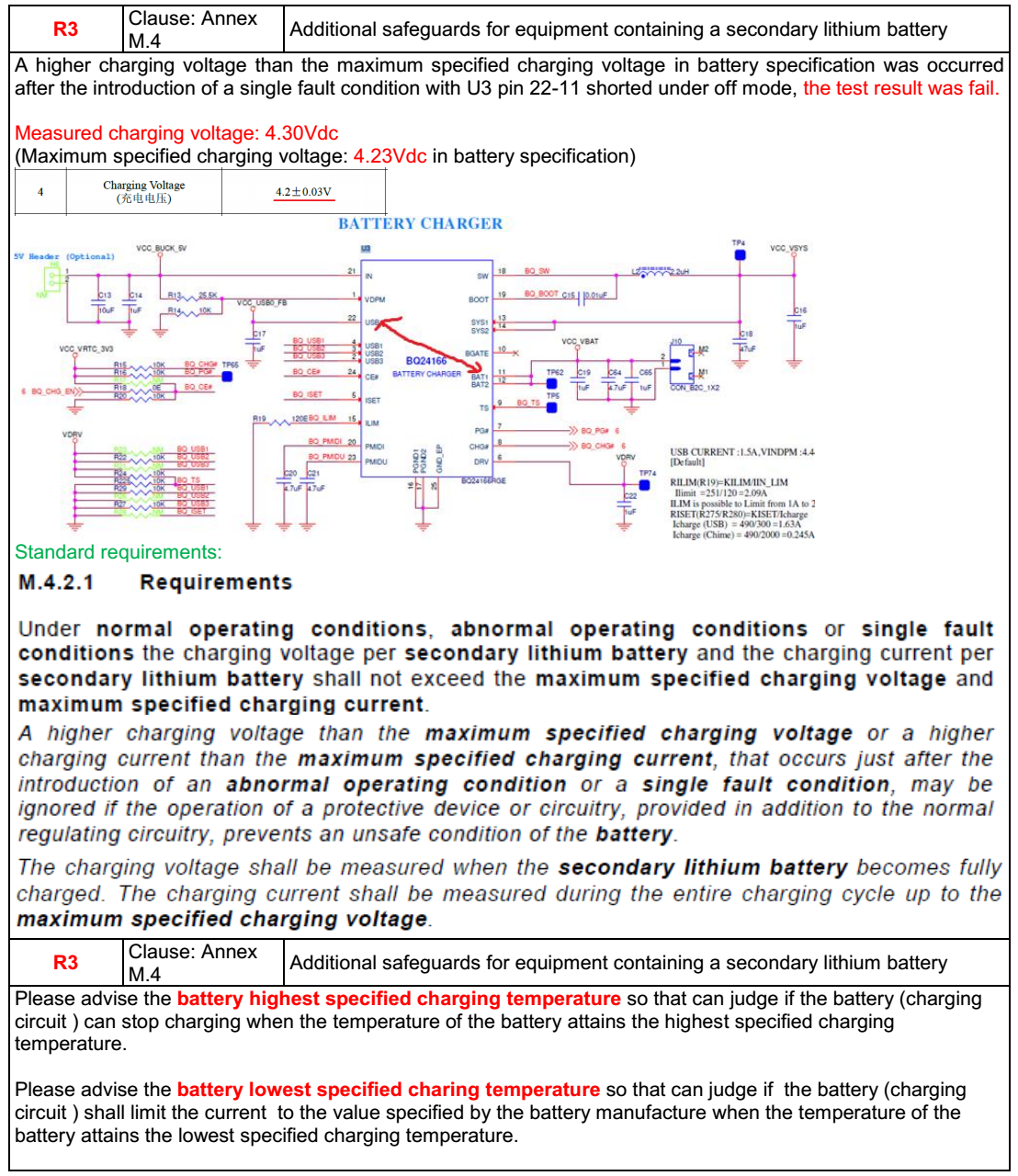
In our design we connect the TS pin with an equal sized resistor divider from DRV to TS to GND. So I would like to know how the TS pin will be functioning in this combination of resistors. Will there be any role of Vwarm and Vcold in this setup. Is there any Temperature control being done in the charger if the Battery does not have a NTC pin. 

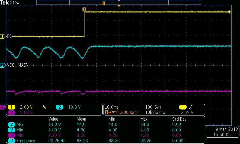
I have one more doubt. We had given our device for certification. We got a feedback from them as mentioned in the attached image. Can you please comment on this. Is there any chance of raising the Vbat voltage to 4.3V as they mentioned?  

We are facing problem in certification due to this. We expect your advise and support. Expecting your reply soon.

  • Hey Johny,

    In regards to your comment about the TS pin resistor divider, two equal-sized resistors should be fine. That will be you a 50%VDRV voltage at TS, results in a TNORMAL temperature. You may also disable the TS functionality by pulling TS to DRV directly. This pushes the TS voltage to above 70%DRV. 

    This is all if you plan on not using an NTC thermistor to monitor the battery temperature.

    In regards to your certification testing, can you clarify a few things for me?

    1) It mentions shorting pin 22 (USB) and pin 11 (BAT). Is this correct? What is the voltage @ USB (pin 22) before the test is performed?

    2) What is meant by "during off mode"? 

    3) Where is the battery charging voltage measured? 

    Regards,

    Joel H

  • Hi Joel,
    Thanks for the response. Can you please explain the TNormal Temperature. What is the threshold of this normal temperature during charging and discharging. Will this affect the performance of the BQ24166 once the battery temperature is above the threshold temperature.
    Regarding the certification testing, i will send you the clarifications on your queries once we discuss that with the Certification Team.
  • Hey Johny,

    I will refer you to Page 5 of the datasheet here: www.ti.com/.../bq24165.pdf where we list in the Electrical Characteristics >> BATTERY-PACK NTC MONITOR.

    Here, we list the %VDRV thresholds that put the charger into TWARM, TCOOL, THOT, and TCOLD. There is also a TSOFF threshold to disable the TS pin. When I say TNORMAL, I mean the temperature that corresponds to a %VDRV between the TWARM and TCOOL (VWARM and VCOOL in the EC table).

    And yes, disabling the TS pin means there is no protection from the charger to disable charging if the battery temperature goes too low or too high. That is why I ask, will you be using the TS functionality to monitor battery temperature and regulate charging? Or will you be doing that elsewhere?


    Regards,
    Joel H
  • Hi Joel,
    We dont get any NTC pins from the Battery. So the battery temperature is not obtained ryt?
    As we have provided 2 equal sized resistors in TS pin, will the ambient temperature at the TS pin do any protection from charger to disable charging? or there is no role of the TS pin unless we get a NTC pin from the Battery.?
  • Hey Johny,

    The TS pin feature of our chargers that utilizes an NTC thermistor to gauge relative temperature of the battery to disable and regulate charging in different temperature regions. 

    As such, the ambient temperature would not play a role unless a separate NTC thermistor was used near the IC or wherever you plan on measuring this temperature. 

    Additionally, the bq24166 also has a Thermal Regulation where it regulates the charge current down when the junction temperature of the IC exceeds a threshold @ 120C typical. This reduces charge current linearly with temperature. If the internal junction temperature continues to rise, the IC shuts off in our Thermal Shutdown mode.

    Regards,

    Joel H

  • Hi Joel,

    Sorry for the delayed response. When we discussed with the certification Team. They have provided us the following inputs. Please find the below attached Image from the Certification team. They are testing by physically shorting the Pin-22 & Pin-11. and Pin-21& Pin-11. At this time the voltage at VUSB and VIN will be 5V simultaneously. This is the method of Testing by them. Can you suggest how we can modify the circuit accordingly to meet their requirement. Below is their mail to us.

    "1. A higher charging voltage than the maximum specified charging voltage was occurred after the introduction of a single fault condition with U3 pin 22-11 shorted under 5Vdc supply condition; Measured charging voltage: 4.98Vdc (Maximum specified charging voltage: 4.20Vdc declared by battery supplier)

    Below is standard requirements:

    2. A higher charging voltage than the maximum specified charging voltage was occurred after the introduction of a single fault condition with U3 pin 21-11 shorted under 24Vac supply condition; Measured charging voltage: 5.12Vdc (Maximum specified charging voltage: 4.20Vdc declared by battery supplier)

    The battery supplier replied that the maximum certification charging voltage of the battery is 4.20V, and cannot be increased or changed the battery charging voltage any more, so need client to modify the product charging circuit and reduced the charging voltage below 4.2Vdc under all operating conditions (normal or abnormal)."

  • Johny,

    The simplest solution is to add a ~4.3V Zener clamping diode and series current limit resistor at BAT to prevent overvoltage. 

  • Hi Jeff,
    Thanks for your suggestion. We will try with that option and check. Also will this solution make any impact in the Charging cycle of the Battery.

    We were also trying to check a solution by giving a 4.2V input to the Battery Charger IC by giving a resistor divider option. The USB input also will be controlled to give a 4.2V . How will this solution make an impact on the charging circuit. also how the VDPM should be set so as to meet this requirement.
  • The zener diode will not affect the charge cycle but will increase leakage current when in battery only mode.

    If you limit the input power to 4.2V, the buck converter will not have enough headroom to provide full charge current when the battery gets close to termination (3.9V-4.0V). Therefore the charge time to 4.2V will be much, much longer than normal. The app note below explains why:

    www.ti.com/.../slyt569

    I am puzzled by this requirement. In my 6 years of supporting battery chargers, I have never heard of this requirement. The single fault of shorted IC pins that are on different sides of the die seems very unlikely. Internally, 2 or more circuits/components would have to fail before BAT would see IN voltage.
  • Hi Jeff,

    We were also facing another issue in the BQ24166 IC. Our device is working in full time battery mode. We are using AC input supply for charging the Battery. The AC supply is rectified using bridge rectifier and the rectified input is given to the TPS54140 Buck regulator. And a 5V output is givrn to the BQ24166. The issue what happens is when we try giving 9VAC. When given to 16VAC it does not have any issue. Also when we give this to constant 7V DC at rectifier side there is no issue. The charger PG# pin is toggling at regular interval of time. The Graph is attached along with.  Some times the supply gets dipped. And the source is not able to give constant supply. Can you please suggest the possible reason for this.Is there anything we can do on the TPS54140 side or the BQ24166 side to avoid this. Attaching the Scheme.

    The graphs of the power lines. The graph shows the PG line pulling up. The Pink line is the 5V buck output and the blue line is the rectified AC input.

  • Is it possible that the charger is pulling more current than the buck can supply? The buck is set for 1.5A but the ILIM for the charger is 2.09A. Do you have the capability to measure the current going into/out of the charger with a current probe? Can you separate the buck from the charger and connect a load to the buck and then connect a separate power supply to the charger? This will help isolate the problem to the buck regulator or the charger.
  • Hi Jeff,
    We tested with several loads. We are giving a rectified AC input to the TPS54140. Following are our observation.
    -When more than 9V supply was provided to the device, it does not have any issue.
    -But when the device is given a 9V or less volt AC input it is behaving like as shown in the earlier image.
    -While it is connected to DC input up-to a minimum of 7V, there is no issue.
    -When the Battery is not connected to the Charger IC there is no issue.

    So with these observation can you find any issue or any problem in the design that we are missing out. Can you please suggest
  • Can you repeat the scope plot but add the charger's inductor current or SW node voltage?