This thread has been locked.

If you have a related question, please click the "Ask a related question" button in the top right corner. The newly created question will be automatically linked to this question.

BQ25895: Charging issue

Part Number: BQ25895

I have made a custom board with BQ25895 on it, but I encounter a charging problem with my board.

If I connect the charging port (VBUS D- D+ and GND) to an adapter with rating 5V 2A, it works okay(it draws 5V 0.45A, I expect it to draw around 2A)

However if I connect it to an adapter that support quick charge, although I can see 12V on the adapter, it automatically disable the BATFET hence there is no current drawn towards the battery.

The load on SYS is only an microcontroller which should not draw more than 30mA. The load on PMID is only a red LED with 2.2kOhm resistor in series.

Any clue would be appreciated!

Here is the registers value when it is not charging:

0x00: 0x3F
0x01: 0x05
0x02: 0x3D
0x03: 0x3A
0x04: 0x20
0x05: 0x13
0x06: 0x5E
0x07: 0x9D
0x08: 0x03
0x09: 0x44
0x0A: 0x93
0x0B: 0xE2
0x0C: 0x80
0x0D: 0x13
0x0E: 0x00
0x0F: 0x00
0x10: 0x00
0x11: 0x00
0x12: 0x00
0x13: 0x3F
0x14: 0x39

Here is the register value when connected to adapter 5V 2A:

0x00: 0x48
0x01: 0x05
0x02: 0x3D
0x03: 0x3A
0x04: 0x20
0x05: 0x13
0x06: 0x5E
0x07: 0x9D
0x08: 0x03
0x09: 0x44
0x0A: 0x93
0x0B: 0x36
0x0C: 0x80
0x0D: 0x0F
0x0E: 0x00
0x0F: 0x00
0x10: 0x00
0x11: 0x94
0x12: 0x00
0x13: 0x48
0x14: 0x39

Here is the register value when connected to adapter that support quick charge:

0x00: 0x1C
0x01: 0x05
0x02: 0x3D
0x03: 0x3A
0x04: 0x20
0x05: 0x13
0x06: 0x5E
0x07: 0x9D
0x08: 0x03
0x09: 0x64
0x0A: 0x93
0x0B: 0x86
0x0C: 0x00
0x0D: 0x54
0x0E: 0x00
0x0F: 0x00
0x10: 0x00
0x11: 0xDE
0x12: 0x00
0x13: 0x08
0x14: 0x39

Update: I tried to change the 0x00 register with 0x25, I sometimes get 5V 0.6A, sometimes I get 5V 0.3A
Here is the register value:

0x00: 0x27
0x01: 0x05
0x02: 0x3D
0x03: 0x3A
0x04: 0x20
0x05: 0x13
0x06: 0x5E
0x07: 0x9D
0x08: 0x03
0x09: 0x44
0x0A: 0x93
0x0B: 0x76
0x0C: 0x00
0x0D: 0x12
0x0E: 0x00
0x0F: 0x00
0x10: 0x00
0x11: 0x97
0x12: 0x00
0x13: 0x48
0x14: 0x79

How can I get the maximum current out from the adapter (i.e. 5V 2A)?

  • Hello Elvin,

    From the registers content you provided, couple things are going on:

    -For the case when you connected a 5V/2A adapter:

    • The D+/D- detection resulted in a 500mA input current limit, and the device is in input current limit (REG13[6]). The device is trying to output the 2A charging current, but it cannot draw any more current from the input.
    • The type of input detected is USB SDP which corresponds to 500mA input current limit.

    -For the case using a quick charge adapter:

    • REG09[5] is being set, disabling both charging and discharging from the battery (Forcing the BATFET off). This bit only is only set by either the host writing to this bit or there is an over-current protection event when the battery discharge current exceeds the OCP limit.

    It seems something is interfering with the D+/D- detection:

    • Do you have any additional circuitry on the D+/D- lines that might affect the result of D+/D- detection? Any pull-down resistors?

    Regarding the BATFET turning off, can you verify there's no short on the battery or the system that might cause an event that trips the OCP?

    Since OTG is always enabled on this configuration, perhaps there is a transient event from the battery during the transition from boost to buck mode that trips the OCP. You could try disabling OTG and see if the behavior is the same.

  • Thanks for the reply Fernando!

    Fernando Lopez Dominguez said:
    • Do you have any additional circuitry on the D+/D- lines that might affect the result of D+/D- detection? Any pull-down resistors?

    Currently the D+/D- is directly and only connected to a USB cable. I didn't know that we need a pull down resistor for D+/D-. However even after I add 15kOhm pulldown resistors to both D+ and D- it still doesn't work.

    Fernando Lopez Dominguez said:

    Since OTG is always enabled on this configuration, perhaps there is a transient event from the battery during the transition from boost to buck mode that trips the OCP. You could try disabling OTG and see if the behavior is the same.

    I have tried disabling the OTG, and I observed similar behavior as the previous one.

    Fernando Lopez Dominguez said:

    Regarding the BATFET turning off, can you verify there's no short on the battery or the system that might cause an event that trips the OCP?

    I have no idea on this issue, I have checked the connections and I found no short on my board.

    Is there a way for me to disable the D+/D- then? I just need it to be able to charge with 5V/2A. I have search through the forum, and I found that I need to short the D+/D- on my board, however I can only draw 5V/0.7A as for now. Is there any register that I need to configure in order to achieve 5V/2A?

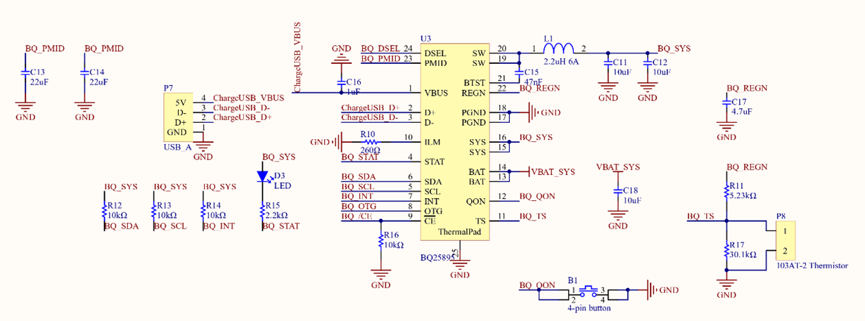
    Below is the circuit diagram of my board if that's helpful:

  • Hello Elvin,

    Just wanted to add some additional clarification, when asking about the pull-downs on D+/D- , the intention was to make sure there wasn't something on the D+/D- lines that might affect the detection. The way D+/D- detection works is a combination of monitoring voltages and sinking currents on the D+/D- lines, so any additional impedance on those lines could cause the thresholds to assimilate those of a different USB Type, but you have already clarified this isn't the case.

    D+/D- detection cannot be disabled, but like you mentioned, you can force the detection to always result in DCP by shorting  the D+/D- lines. Having said that, it's important to understand how input current limit works in this device: the input current limit used is the smallest value between the I2C register value and the ILIM pin setting. From your schematic, it looks like the ILIM is set to ~1.5A. However, in the example of your 5V/2A adapter, the I2C register is being set to 500mA as the result from the D+/D- detection which found a SDP, hence why your input is being limited.

    You can overwrite the resulting input current limit from the detection by writing to the I2C register once the detection is done.

    Other items to verify are the following:

    • What is the charge current and battery voltage during your testing? Reason to verify this is to make sure we are in the correct phase of the charge cycle and not for example in the CV region where you won't get the full constant current value.
    • Is there a significant amount of output impedance that might force the device into the constant voltage mode earlier?
    • How long is the cable for your adapters? Too long of a cable might cause excessive voltage drop at the input of the device or inductance kicks that might trip faults.
    • Is your device heating up excessively? Would like to rule out thermal regulation. Bit REG0E[7] lets you know if thermal regulation trips.